Eureka AIR delivers breakthrough ideas for toughest innovation challenges, trusted by R&D personnel around the world.

Method and system for producing lng from waste pyrolysis gas

A technology for pyrolysis of gas and waste, used in gas fuels, special forms of dry distillation, petroleum industry, etc., can solve the problems of dioxin production, improve the hydrogen-carbon ratio, change the pyrolysis process, avoid dioxin and secondary The effect of pollution

Active Publication Date: 2017-08-25
SHENWU TECH GRP CO LTD
View PDF2 Cites 0 Cited by
  • Summary
  • Abstract
  • Description
  • Claims
  • Application Information

AI Technical Summary

Problems solved by technology

However, the disadvantage of this method is that although there is a purification process for removing dioxins, dioxins will still be produced; at the same time, this process generates pyrolysis oil, which needs to be treated and operated

Method used


Image

  • Method and system for producing lng from waste pyrolysis gas
  • Method and system for producing lng from waste pyrolysis gas
  • Method and system for producing lng from waste pyrolysis gas

Examples


Embodiment 1

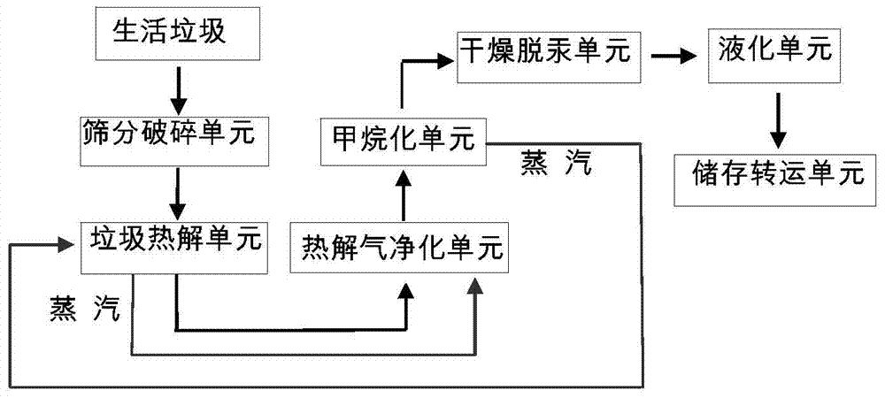
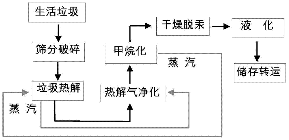
[0047] See figure 1 , figure 2 , the system for producing LNG includes a screening and crushing unit, a garbage pyrolysis unit, a pyrolysis gas purification unit, a methanation unit, a drying unit and a liquefaction unit, and the above units are connected in sequence;

[0048] Wherein, the garbage pyrolysis unit includes a garbage pyrolysis device, the flue gas outlet of the garbage pyrolysis device is connected with a waste heat boiler, and the solid material outlet of the garbage pyrolysis device is connected with a combustion device; the pyrolysis gas purification The unit includes a washing tower, a heavy hydrocarbon removal tower, an absorption tower and a deoxygenation reactor connected in sequence; the drying unit includes drying equipment and mercury removal equipment connected in sequence, and the liquefaction unit includes a low-temperature heat exchanger and a gas-liquid separator connected in sequence , Distillation tower and storage tank. The garbage pyrolysis ...

Embodiment 2

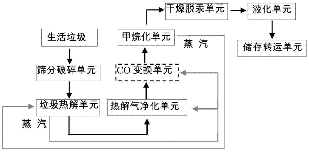
[0060] See image 3 with Figure 4 , compared with the system of Example 1, the system of this embodiment also includes a CO conversion unit, the CO conversion unit is arranged between the pyrolysis gas purification unit and the methanation unit, and the CO conversion unit includes sequentially connected oil-water separation device, mixer, heat exchanger, shift furnace, and water cooler and gas-liquid separator connected through pipelines; wherein, the heat exchanger is a tube heat exchanger, and the gas outlet of the shift furnace is connected to the The heating medium inlet of the heat exchanger, the heating medium outlet of the heat exchanger is connected to the water cooler.

[0061] The production of LNG from waste pyrolysis gas includes the following steps:

[0062] 1. Sieving and crushing: same as embodiment 1 of the present invention.

[0063] 2. Garbage pyrolysis: The municipal solid waste with a particle size of 3-5mm after crushing is sent to the garbage pyrolysi...


PUM


Abstract

The present invention proposes a method for producing LNG from garbage pyrolysis gas, including steps: 1) screening and crushing garbage; Pyrolysis gas purification: The garbage pyrolysis gas from the compressor enters the bottom of the washing tower and contacts with the lye countercurrently to remove HCl gas; 4) Methanation: Methane is generated through a reactor equipped with a nickel catalyst; 5) Drying and mercury removal; 6) Liquefaction: The methane gas from the drying unit enters the liquefaction unit, the methane is liquefied with a mixed refrigerant, the liquid phase part is subjected to low-temperature rectification, and the LNG product is obtained from the tower kettle. The method proposed by the invention has the advantages of simple operation, small methane loss, and the gas produced meets the gas quality index requirement of LNG for raw gas. Through the combination of waste pyrolysis technology, methanation technology and heat energy recovery technology, solid waste treatment is realized, dioxin and secondary pollution are avoided, and comprehensive utilization of heat energy resources is realized.

Description

technical field [0001] The invention belongs to the field of fuels, and in particular relates to a method and a system for preparing liquid hydrocarbon mixtures through garbage pyrolysis. Background technique [0002] Resources and the environment are the two major themes of the 21st century, and municipal solid waste disposal is an important topic in these two themes. With the enhancement of people's awareness of environmental resources and the improvement of the technical standards of garbage disposal by governments of various countries, the three main methods of traditional garbage disposal, landfill, composting and incineration, have increasingly shown their defects. The treatment capacity is small, the efficiency is low, and the incineration method is prone to secondary pollution, especially the pollution of dioxins, which hinders its industrial application. The waste fluidized bed pyrolysis and gasification process is carried out in an oxygen-free atmosphere, so that ...

Claims


Application Information

Patent Timeline
Patent Type & Authority Patents(China)
IPC IPC(8): C10L3/08C10L3/10C10B53/00
Inventor 史雪君余海鹏闫琛洋车中山杜少春吴道洪
Owner SHENWU TECH GRP CO LTD
Why Eureka
Eureka Blog
Learn More