

LED (light-emitting diode) lamp filament
A technology of LED filaments and LED chips, which is applied in the direction of semiconductor devices, electrical components, circuits, etc., can solve the problems affecting the light efficiency and life of LED filaments, and the heat of LED chips cannot be quickly dissipated, so as to improve the light output angle and light output efficiency. Production The effect of high efficiency and yield rate, simple process
- Summary
- Abstract
- Description
- Claims
- Application Information
AI Technical Summary
Problems solved by technology
Method used
Image

Examples
Embodiment 1
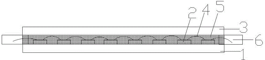
[0037] Such as figure 1 As shown, the present embodiment provides an LED filament, the filament is in an elongated strip structure, the length of the filament is 30mm, the width is 3mm, and the height is 2.5mm. The filament includes a bottom plate 1 , a cover plate 3 , an LED chip 2 , an adhesive 5 and an electrode 6 . The bottom plate 1 and the cover plate 3 are polycarbonate (PC) boards, and 9% yellow phosphor is mixed in the PC boards. Chips 2 are fixed on the base plate 1 , and the chips 2 are connected in series through metal leads 4 and connected to electrodes 6 . The base plate 1 and the cover plate 3 are joined together by an adhesive 5 . The adhesive 5 is epoxy resin, and 9% yellow phosphor powder is mixed in the adhesive 5 .
Embodiment 2
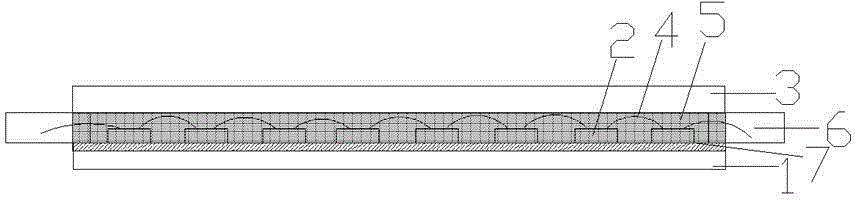
[0039] Such as figure 2 As shown, this embodiment provides an LED filament, the filament is in a long and thin strip structure, the length of the filament is 20mm, the width is 2mm, and the height is 2mm. The filament includes a bottom plate 1 , a cover plate 3 , an LED chip 2 , an adhesive 5 and an electrode 6 . The bottom plate 1 and the cover plate 3 are PC boards, and the PC boards are mixed with 8% yellow phosphor powder and 2% red phosphor powder by mass, and aluminum nitride powder as a heat dissipation material. Chips 2 are fixed on the base plate 1 , and the chips 2 are connected in series through metal leads 4 and connected to electrodes 6 . The base plate 1 and the cover plate 3 are joined together by an adhesive 5 . The binder 5 is silica gel, and the binder 5 is mixed with yellow phosphor powder with a mass ratio of 8% and red phosphor powder with a mass ratio of 2%, and aluminum nitride powder as a heat dissipation material, wherein the aluminum nitride powder...
Embodiment 3
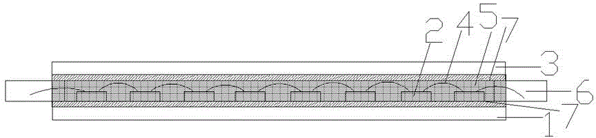
[0041] Such as image 3 As shown, this embodiment provides an LED filament, and the filament includes a bottom plate 1 , a cover plate 3 , an LED chip 2 , an adhesive 5 , and an electrode 6 . The bottom plate 1 and the cover plate 3 are polytetrafluoroethylene plates, which are mixed with 9% yellow fluorescent powder and diamond powder as a heat dissipation material. Chips 2 are fixed on the bottom plate 1 , and the chips 2 are connected in series through metal leads 4 and connected to electrodes 6 . The base plate 1 and the cover plate 3 are joined together by an adhesive 5 . The binder 5 is epoxy resin, and the binder 5 is mixed with 9% yellow fluorescent powder and diamond powder as a heat dissipation material, wherein the mass percentage of the diamond powder is 1%. The upper surface of the base plate 1 and the lower surface of the cover plate 3 are sputtered with a transparent inner surface heat dissipation layer 7, and the inner surface heat dissipation layer 7 is a di...
PUM
| Property | Measurement | Unit |
|---|---|---|
| Length | aaaaa | aaaaa |
| Width | aaaaa | aaaaa |
| Height | aaaaa | aaaaa |
Abstract
Description
Claims
Application Information