Reciprocating type exhaust gas pyrolysis furnace

A waste gas heating and reciprocating technology, which is applied to lighting and heating equipment, combustion using block fuel and gaseous fuel, and combustion methods, etc., can solve the problem of incomplete combustion of combustible gases such as coal and CO, and toxic and harmful substances Or decomposition, high-temperature flue gas vortex intensity in the furnace combustion chamber, low flue gas flow rate, and short residence time of coal combustion, etc., to achieve the effects of improving thermal radiation ability, low operating cost, good quality, stable and reliable

Inactive Publication Date: 2015-08-05
陆骏
View PDF7 Cites 2 Cited by
  • Summary
  • Abstract
  • Description
  • Claims
  • Application Information

AI Technical Summary

Problems solved by technology

[0002] At present, all incinerators on the market that incinerate municipal waste and industrial waste with calorific value use secondary combustion chambers for the treatment of toxic and harmful substances such as dioxins, all of which rely entirely on oil and gas burners to provide heat, and the operating costs are extremely high; in addition, The furnace combustion chamber of the existing secondary combustion chamber does not have a furnace arch layout structure, the residence time of the coal burning inside the furnace combustion chamber is short, and the high-temperature flue gas vortex intensity and flue gas flow rate inside the furnace combustion chamber are low. All of these will lead to insufficient combustion or decomposition of combustible gases such as coal and CO and toxic and harmful substances in the furnace combustion chamber, which will increase the consumption of coal and is not conducive to cost reduction.

Method used


Image

  • Reciprocating type exhaust gas pyrolysis furnace

Examples


Embodiment Construction

[0032] In order to make the object, technical solution and advantages of the present invention clearer, the present invention will be further described in detail below in conjunction with the accompanying drawings and embodiments. It should be understood that the specific embodiments described here are only used to explain the present invention, not to limit the present invention.

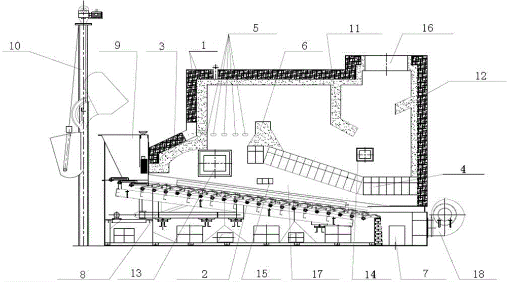
[0033] In a preferred embodiment of the present invention, a reciprocating waste gas pyrolysis furnace, such as figure 1 As shown, it includes a furnace wall shell 1 that encloses a furnace combustion chamber 17, and the bottom of the furnace combustion chamber 17 is obliquely provided with a reciprocating grate 2 and a grate power mechanism 8 for driving the reciprocating grate 2;

[0034] The inner front end and the inner rear end of the above-mentioned furnace wall shell 1 are respectively provided with a front furnace arch 3 and a rear furnace arch 4, and the front furnace arch 3 and the rear f...


PUM


Abstract

The invention discloses a reciprocating type exhaust gas pyrolysis furnace. The furnace comprises a furnace wall housing forming a hearth combustion chamber, the bottom of the hearth combustion chamber is inclinedly provided with a reciprocating type fire grate and a fire grate power mechanism for driving the reciprocating type fire grate, an inner side front end and an inner side rear end of the furnace wall housing are respectively provided with a front furnace arch and a rear furnace arch, the front furnace arch and the rear furnace arch are located above the reciprocating type fire grate, multiple C-shaped exhaust gas injection pipes are arranged between the front furnace arch and the rear furnace arch, the top of the furnace wall housing is provided with a high-temperature flue gas outlet, the bottom of the furnace wall housing is provided with a slag outlet, the rear furnace arch is prepared from arch bricks by bricklaying, and a fireproof concrete layer is casted on the surface of the rear furnace arch. The reciprocating type exhaust gas pyrolysis furnace has a low operation cost and can fully burn or decompose combustible gas such as fire coal and CO and poisonous and harmful substances in the hearth combustion chamber.

Description

technical field [0001] The invention relates to a waste gas pyrolysis furnace, in particular to a reciprocating waste gas pyrolysis furnace. Background technique [0002] At present, all incinerators on the market that incinerate municipal waste and industrial waste with calorific value use secondary combustion chambers for the treatment of toxic and harmful substances such as dioxins, all of which rely entirely on oil and gas burners to provide heat, and the operating costs are extremely high; in addition, The furnace combustion chamber of the existing secondary combustion chamber does not have a furnace arch layout structure, the residence time of the coal burning inside the furnace combustion chamber is short, and the high-temperature flue gas vortex intensity and flue gas flow rate inside the furnace combustion chamber are low. All of these will lead to combustible gases such as coal and CO and toxic and harmful substances not being fully burned or decomposed inside th...

Claims


Application Information

Patent Timeline
Patent Type & Authority Applications(China)
IPC IPC(8): F23C1/04F23M5/06
CPCY02W10/40
Inventor 陆骏尹晓伟
Owner 陆骏
Why Eureka
Try Eureka