Vibration measurement apparatus based on laser speckle of polarized singular-point light beam
What is Al technical title?
Al technical title is built by PatSnap Al team. It summarizes the technical point description of the patent document.
A laser speckle and vibration measurement technology, applied in the optical field, can solve the problems of difficult functions, high process requirements, inconvenient use, etc., and achieve the effects of diverse shapes and materials, strong anti-interference ability and high sensitivity
Active Publication Date: 2015-08-05
上海微鸢电子科技有限公司
View PDF8 Cites 7 Cited by
Summary
Abstract
Description
Claims
Application Information
AI Technical Summary
This helps you quickly interpret patents by identifying the three key elements:
Problems solved by technology
Method used
Benefits of technology
Problems solved by technology
[0003] There is a vibration information detection method in the prior art, a piezoelectric vibration sensor, (see US patent, patent name: Piezoelectric vibration sensor, inventor: Orten Birger, patent number: US7656524B2, patent authorization time: May 06, 2008 ), although there are certain characteristics, but there are still essential deficiencies: 1) Use the piezoelectric principle for vibration detection, and make a vibration sensor based on piezoelectric materials, and then the vibration sensor is in contact with the detected object to sense the vibration information, so in essence it needs The piezoelectric sensor and the detected vibration object are in close contact, and long-distance vibration telemetry cannot be realized; 2) The piezoelectric vibration sensor and the detected object are used in close proximity, and the dete
Method used
Image
Click on the blue label to locate the original text in one second.
Reading with bidirectional positioning of images and text.
Examples
Embodiment Construction
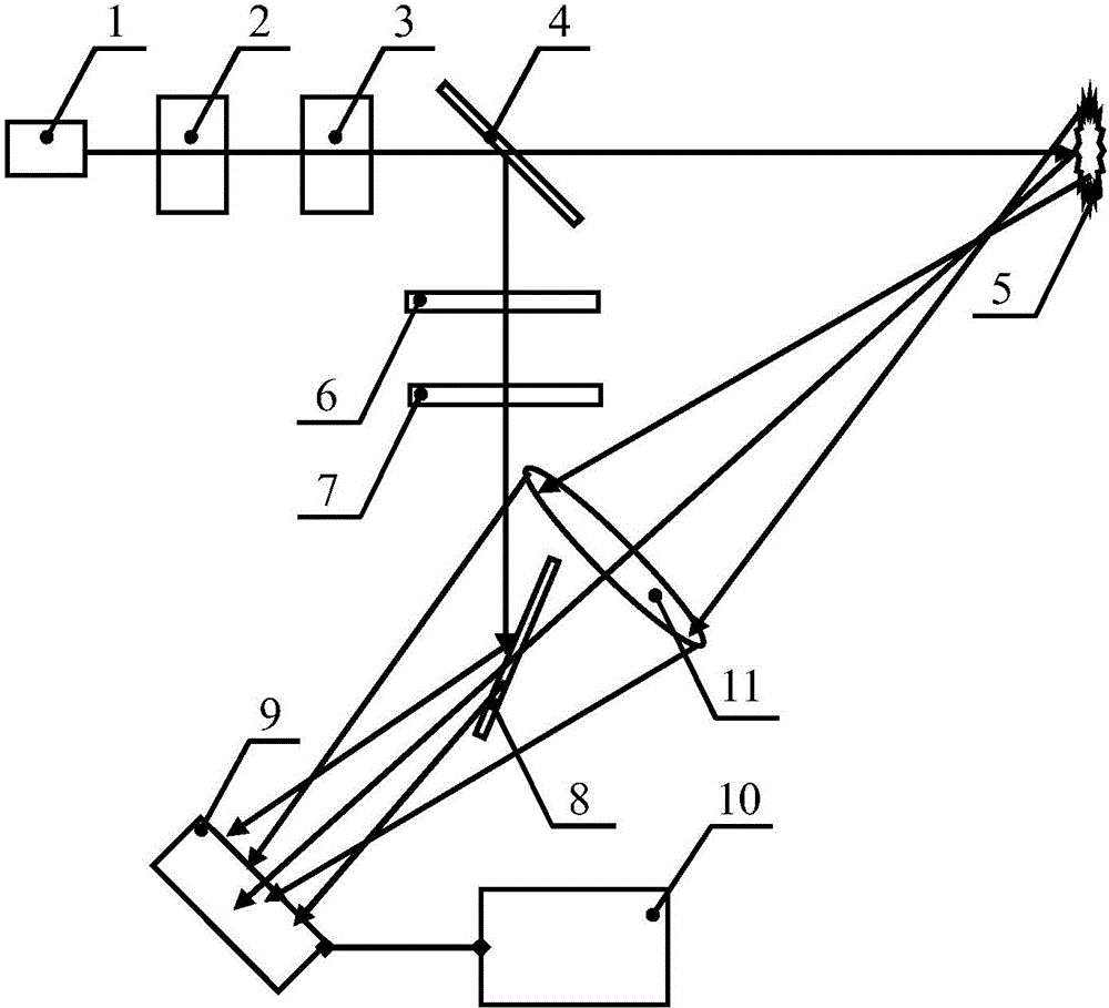
[0022] The present invention will be further described below in conjunction with drawings and embodiments.
[0023] Such as figure 1 As shown, a vibration measurement device based on laser speckle of polarized singular point beam combines the principle of laser speckle excited by polarized singular point beam and vector light field coherence technology. area, the laser scattering effect of the singular point beam occurs in the detected area, and the laser speckle is transmitted through the defocused optical imaging system; after splitting, another polarized singular point beam passes through two wave plates, and the transverse polarization state distribution is adjusted and then reflected by the reflective element Finally, there is an overlapping area with the laser speckle light field to form an interference light field. The photoelectric sensor detects the interference light field information, and obtains vibration information through information processing.
[0024...
PUM
Abstract
The invention relates to a vibration measurement apparatus based on a laser speckle of a polarized singular-point light beam. With the apparatus, a problem that non-destructive telemetering of vibration information can not be realized in the prior art can be solved. On the basis of the principle of laser speckle excitation by the polarized singular-point light beam and combination with a vector-light field coherent technology, a vector light field coherent technology passes through a light splitter and then irradiates a detected zone; a singular-point light beam laser scattering effect is generated by the detected zone; and a laser speckle passes through an out-of focus optical imaging system to carry out transmission. Another polarized singular-point light beam after light splitting passes through two wave plates; horizontal polarized distribution control is carried out and then reflection is carried out by a reflection element; an overlapped area with a laser speckle light filed exists to form an interference light field; and a photoelectric sensor detects the interference light field information and vibration information is obtained based on information processing. According to the invention, the vibration measurement apparatus has characteristics of non-contact detection, non-destructive detection, remote measurement realization, adjustable performance, high sensitivity and reliability, good anti-interference capability, wide frequency response characteristic, high information quantity, easy system construction, convenient usage, and wide application range and the like.
Description
technical field [0001] The invention belongs to the field of optical technology, and relates to a vibration detection method, in particular to a vibration measurement device based on a polarized singularity beam laser speckle, which is mainly used in noise analysis, vibration monitoring, voice collection, engineering testing, risk assessment, environmental Vibration information measurement in perception, quality inspection, environmental monitoring, resource exploration, biological life, medical treatment, smart health, process control, national defense security, Internet of Things, process control, advanced manufacturing, etc. Background technique [0002] Vibration is a very common and important physical phenomenon that exists widely in our environment. In a broad sense, vibration also includes the fields of acoustics and audio. Vibration measurement has a wide range of applications in many fields. For example, in the field of engineering testing, the vibration of engineer...
Claims
Application Information
Patent Timeline
Application Date:The date an application was filed.
Publication Date:The date a patent or application was officially published.
First Publication Date:The earliest publication date of a patent with the same application number.
Issue Date:Publication date of the patent grant document.
PCT Entry Date:The Entry date of PCT National Phase.
Estimated Expiry Date:The statutory expiry date of a patent right according to the Patent Law, and it is the longest term of protection that the patent right can achieve without the termination of the patent right due to other reasons(Term extension factor has been taken into account ).
Invalid Date:Actual expiry date is based on effective date or publication date of legal transaction data of invalid patent.