On-site repair and surfacing method for large-area metal walls

A large-area metal and on-site repair technology, which is applied to metal processing equipment, welding equipment, arc welding equipment, etc., can solve the problems of accumulation forming failure, welding machine ground wire cannot be conveniently pressed, etc., to ensure stability and good stacking The effect of welding layer accumulation morphology and soft texture

Inactive Publication Date: 2016-04-20
NANHUA UNIV
View PDF5 Cites 0 Cited by
  • Summary
  • Abstract
  • Description
  • Claims
  • Application Information

AI Technical Summary

Problems solved by technology

[0004] The purpose of the present invention is to overcome above-mentioned weak point, and provide a kind of large-area metal wall surface repair surfacing welding method and surfacing welding device, to solve the current large-area metal wall surface in-situ repair welding process, the molten pool is easy to fall under the action of gravity. The problem of accumulation forming failure due to downflow and the ground wire of the welding machine cannot be conveniently pressed against the wall

Method used


Image

  • On-site repair and surfacing method for large-area metal walls
  • On-site repair and surfacing method for large-area metal walls
  • On-site repair and surfacing method for large-area metal walls

Examples


Embodiment 1

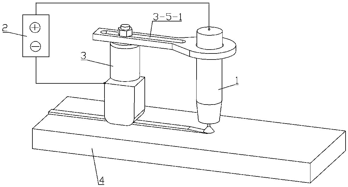
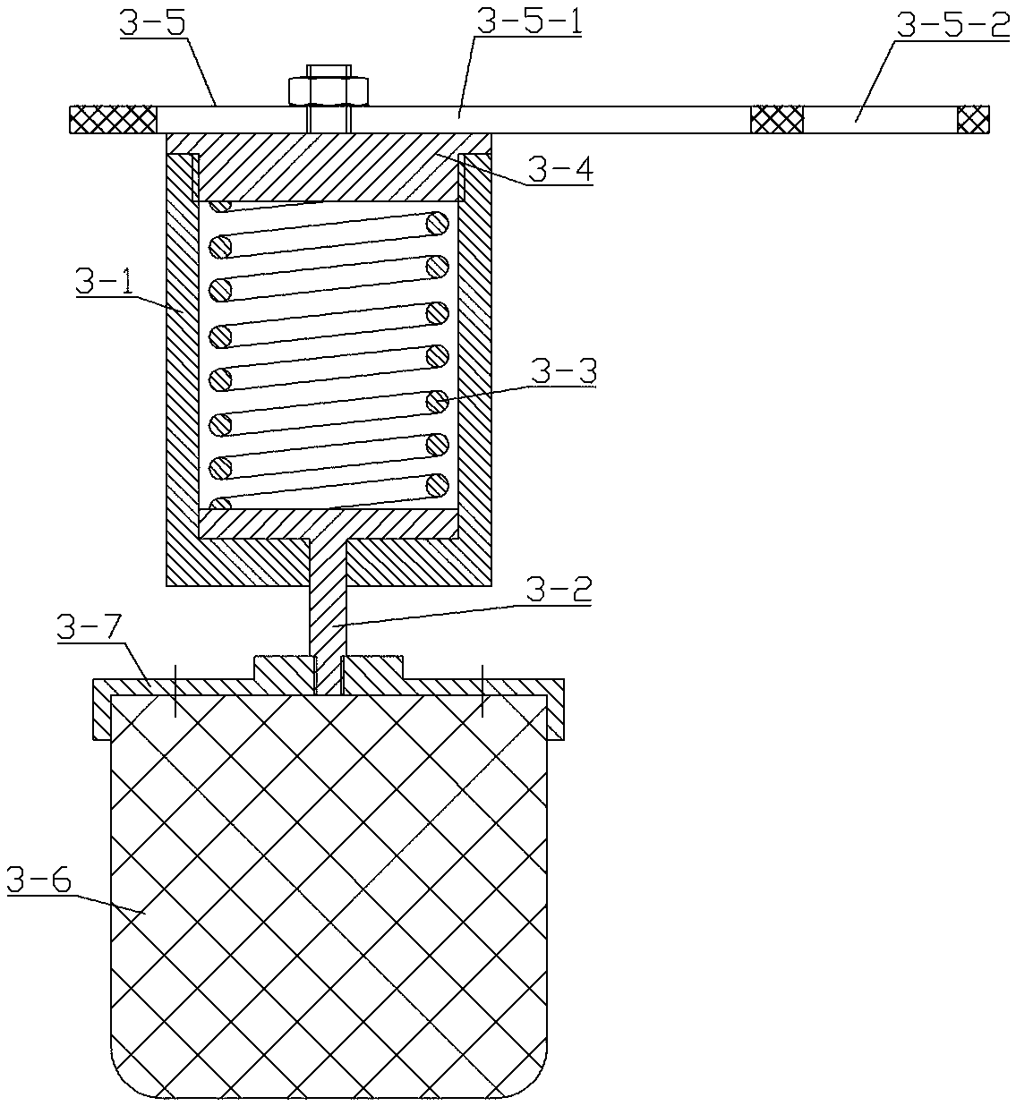
[0043] Such as figure 1 , 2 Shown, a kind of on-the-spot overlay welding method of metal wall surface repair of a large area, install synchronous moving mechanism 3 on the welding torch 1 in the surfacing device, during the surfacing process, the graphite slide block 3-6 on the synchronous moving mechanism 3 is in melting all the time. The rear of the pool, and is pressed on the surfacing layer by the elastic pressing mechanism on the synchronous moving mechanism, and moves together with the welding torch 1. The welding current enters the workpiece from the welding wire of the welding torch through the arc, and then returns to the welding machine from the graphite slider 3-6 Negative pole of power supply 2;

[0044] The specific welding steps are as follows:

[0045] S01, perform simple mechanical polishing on the welding surface of the surfacing workpiece, and remove rust, water and oil;

[0046] S02, the welding torch 1 approaches the workpiece 4 to be surfacing, when the...

Embodiment 2

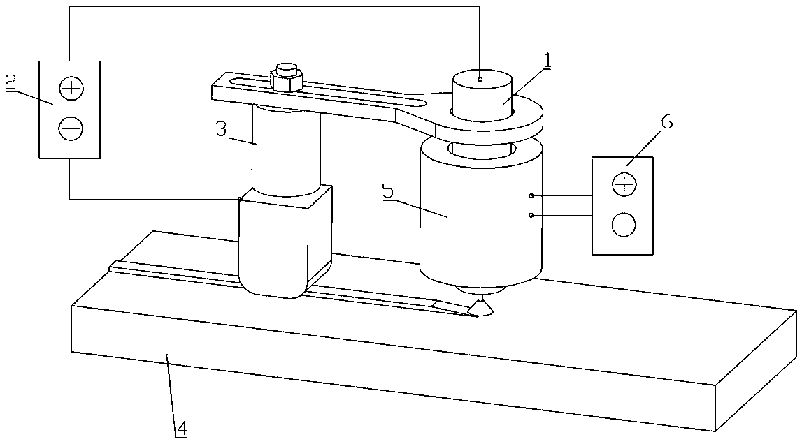
[0055] Such as image 3 As shown, the only difference between this embodiment and embodiment 1 is that the longitudinal magnetic field coil 5 is installed on the welding torch 1, and the longitudinal magnetic field coil 5 is connected with the longitudinal magnetic field AC power supply 6, and the frequency of the AC power supply is 7-15 Hz. The longitudinal magnetic field coil 5 generates a longitudinal magnetic field in the molten pool area, and the longitudinal magnetic field forms rotating electromagnetic stirring on the molten pool, and the stirring flow impacts the crystallization front, fuses the dendrites, and refines the grains.

Embodiment 3

[0057] Such as Figure 4~6 As shown, the difference between this embodiment and Embodiment 1 is only that a transverse magnetic field generating device is installed on the connecting plate 3-5 of the synchronous moving mechanism 3, and the coil 8-2 of the transverse magnetic field generating device is connected with the DC power supply 7, A constant transverse magnetic field pointing to the right side of the welding traveling direction is generated during the surfacing process, and the strength of the transverse magnetic field is between 100 and 200 gauss. The transverse magnetic field promotes the backward transport of the melt, improves the acceptability of the molten pool to the droplet, and makes the arc deflect in the direction opposite to the direction of the welding torch. dramatically decrease.

[0058] The transverse magnetic field generating device includes a DC power supply 7, a first iron core 8-1, a second iron core 8-4, a transverse magnetic field coil 8-2 and a...


PUM


Abstract

The invention provides a large-area metal wall surface field patching surfacing welding method. A synchronous moving mechanism is installed on a welding gun of a surfacing welding device, in a surfacing welding process, a graphite sliding block on the synchronous moving mechanism is always located at the back of a welding pool and tightly pressed onto a surface welding layer by an elastic pressing mechanism on the synchronous moving mechanism, the graphite sliding block moves together with the welding gun, and welding current enters into a workpiece through electric arcs from a welding wire of the welding gun and returns to the welding machine power source negative pole from the graphite sliding block. The surfacing welding device comprises the welding gun, a welding machine power source and the synchronous moving mechanism. The synchronous moving mechanism comprises an elastic pressing mechanism and an insulation connecting plate. The elastic pressing mechanism comprises a shell, a pushing plate, a spring, an end cap, the graphite sliding block and a concave disk, and in surfacing welding, the spring generates a pressing force on the graphite sliding block. According to the large-area metal wall surface field patching surfacing welding method, the graphite sliding block is used for achieving the moving type connection between welding machine ground wires and the workpiece, the backward current distribution in the welding pool is strengthened, and combined with an externally added transverse magnetic field or a longitudinal magnetic field, the problems of the welding pool instability and organizational regulation and control caused by the gravity of metal wall surface field patching surfacing welding are solved.

Description

technical field [0001] The invention relates to welding technology, in particular to a large-area metal wall surface on-site repair surfacing welding method and a surfacing welding device. Background technique [0002] Large metal walls are commonly found in factories and large machinery, such as nuclear power plants and ship hulls. With the increase of service age, these metal walls may have problems such as environmental corrosion, fatigue cracks or external force damage. At this time, it is necessary to carry out on-site repair by means of melting electrode arc and other methods. [0003] At present, the problems faced by on-site repair welding of large-area metal walls are as follows: 1. The connection between the welding machine ground wire and the metal wall surface: most metal walls are in a vertical state, and the surface is smooth, and a special device is required to press the welding machine ground wire on On the wall; 2. It belongs to the all-position welding co...

Claims


Application Information

Patent Timeline
Patent Type & Authority Patents(China)
IPC IPC(8): B23K9/04B23K9/235
CPCB23K9/04B23K9/235
Inventor 柏兴旺张海鸥周祥曼潘风清
Owner NANHUA UNIV
Why Eureka
Try Eureka