Ultrahigh-pressure water jet cutting machine nozzle

A water cutting machine, ultra-high pressure technology, applied in spray guns, explosion generating devices, abrasives, etc., can solve the problems of low cutting efficiency, low cutting speed, and small water specific gravity, and achieve strong erosion and material removal capabilities. Increase cutting efficiency and specific gravity effect

Active Publication Date: 2015-08-12
重庆新锐科技服务有限公司
View PDF6 Cites 4 Cited by
  • Summary
  • Abstract
  • Description
  • Claims
  • Application Information

AI Technical Summary

Problems solved by technology

However, the shortcomings of the ultra-high pressure water jet cutting machine are also very obvious, mainly in that: it uses water as the cutting medium, the specific gravity of wa

Method used


Image

  • Ultrahigh-pressure water jet cutting machine nozzle
  • Ultrahigh-pressure water jet cutting machine nozzle
  • Ultrahigh-pressure water jet cutting machine nozzle

Examples


Embodiment 1

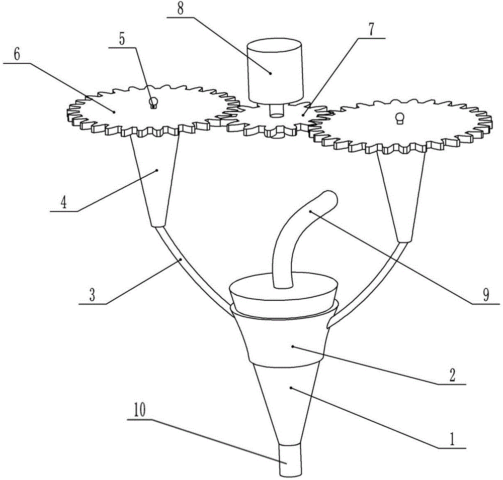
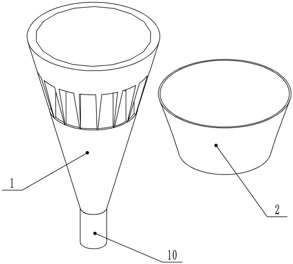
[0027] Such as figure 1 As shown, the present embodiment provides a nozzle for an ultra-high pressure water cutting machine, including a hollow nozzle body 1, the nozzle body 1 is conical, such as figure 2 As shown, the side wall is processed with several through holes. The sealing sleeve 2 is set on the nozzle body 1. The sealing sleeve 2 can rotate and seal the outer wall of the nozzle body 1. The liquid outlet (lower end) of the nozzle body 1 is provided with a guide channel 10. The diameter of the guide channel 10 is equal to that of the nozzle body. 1 The aperture of the liquid outlet, the length of the guide channel is equal to 2-3 times the aperture. The upper end of the nozzle body 1 communicates with the high-pressure water pipe 9 .

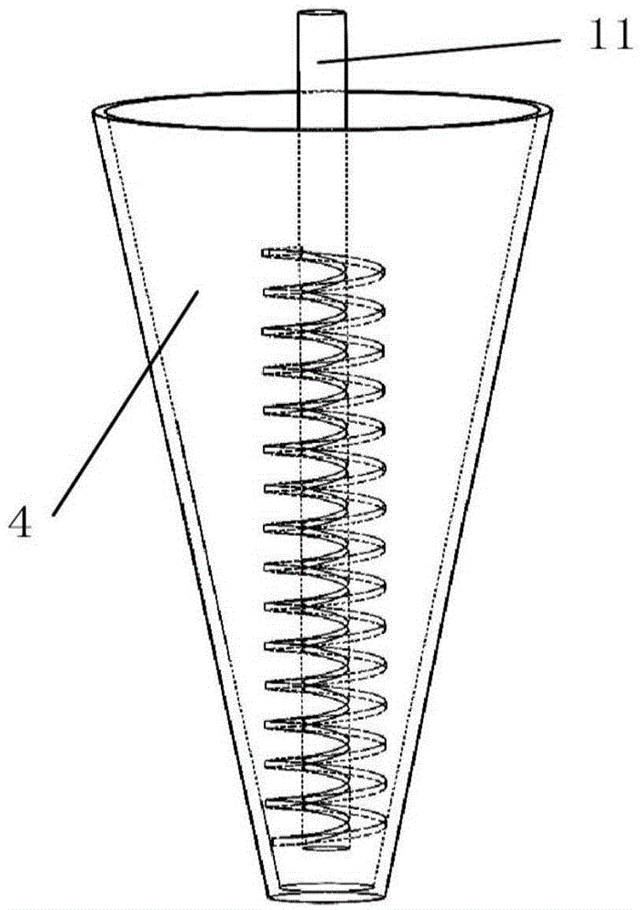
[0028] Such as figure 1 and image 3 As shown, the abrasive device includes a spiral reamer 11, a transmission gear 6 and a conical hollow cylinder 4. The hollow cylinder 4 is provided with a feed port and a discharge pipe 3, and th...

Embodiment 2

[0031] Such as Figure 4 As shown, the difference between this embodiment and Embodiment 1 is that the discharge pipe 3 is a pipe with higher hardness, and the two rotating shafts 5 and the driving motor 10 are all welded on the rotating disk 12, and the rotating disk 12 is welded with a rotating handle or turn the motor.

[0032] During operation, since the sealing sleeve 2 is sleeved on the nozzle body 1 and can rotate, the rotating disc 12 can drive the abrasive device to rotate, so the discharge pipe 3 is still rotating while discharging, and the abrasive can be rotated from different directions. Mix into high pressure water for more even mixing and better results.


PUM


Abstract

The invention belongs to the technical field of high-pressure water jet cutting machines, and particularly discloses an ultrahigh-pressure water jet cutting machine nozzle. The ultrahigh-pressure water jet cutting machine nozzle comprises a conical hollow nozzle body and a material grinding device, wherein the material grinding device is used for transporting a grinding material and comprises a spiral reamer, a drive gear and a conical hollow cylinder body; the hollow cylinder body is provided with a material inlet and a discharge pipe communicated with a nozzle body; the spiral reamer is arranged in the hollow cylinder body; one end of the drive shaft is fixedly connected with a material receiving end of the spiral reamer, and the other end of the drive shaft is provided with the drive gear; an output end of a driving motor is provided with a driving gear which is meshed with drive gears on the first drive shaft and the second drive shaft; a guide channel is communicated with a liquid outlet of the nozzle body; the pore diameter of the guide channel is equal to the pore diameter of a liquid outlet of the nozzle body; the length of the guide channel is equal to 2-3 times of the pore diameter. Compared with the traditional ultrahigh-pressure water jet cutting machine, the cutting machine is used for mixing grinding materials with high-pressure water skillfully, and water and the grinding materials act as the cutting media together, so that the cutting efficiency is enhanced.

Description

technical field [0001] The invention belongs to the technical field of high-pressure water cutting machines, and in particular relates to a nozzle of an ultra-high-pressure water cutting machine. Background technique [0002] Ultra-high pressure water cutting, also known as water jet and water jet, is a high-energy water flow generated by ordinary water after multi-stage pressurization, and then passes through a very fine ruby ​​nozzle (Φ0.1-0.35mm), Jet cutting at a speed of nearly a thousand meters, this cutting method is called ultra-high pressure water cutting. Its working principle is: after the water stored in the water tank is treated by the filter, it is pumped out by the water pump and sent to the accumulator, and the hydraulic mechanism drives the supercharger to increase the water pressure, and the high-pressure water is sprayed through the controller valve and the nozzle Go to the processing part on the workpiece and cut. [0003] Compared with the traditional ...

Claims


Application Information

Patent Timeline
IPC IPC(8): B24C7/00B24C5/00
CPCB24C5/04B24C7/0007
Inventor 杨盛强
Owner 重庆新锐科技服务有限公司
Why Eureka
Try Eureka