Generator utilizing acoustic energy and sound transducer
A sound energy and generator technology, applied in the direction of sensors, friction generators, sensor components, etc., can solve the problems of no collection, limited application range, small sensitivity distortion, etc., to reduce the loss of sound energy and improve the utilization of sound energy efficiency effect
- Summary
- Abstract
- Description
- Claims
- Application Information
AI Technical Summary
Problems solved by technology
Method used
Image

Examples
Embodiment 1
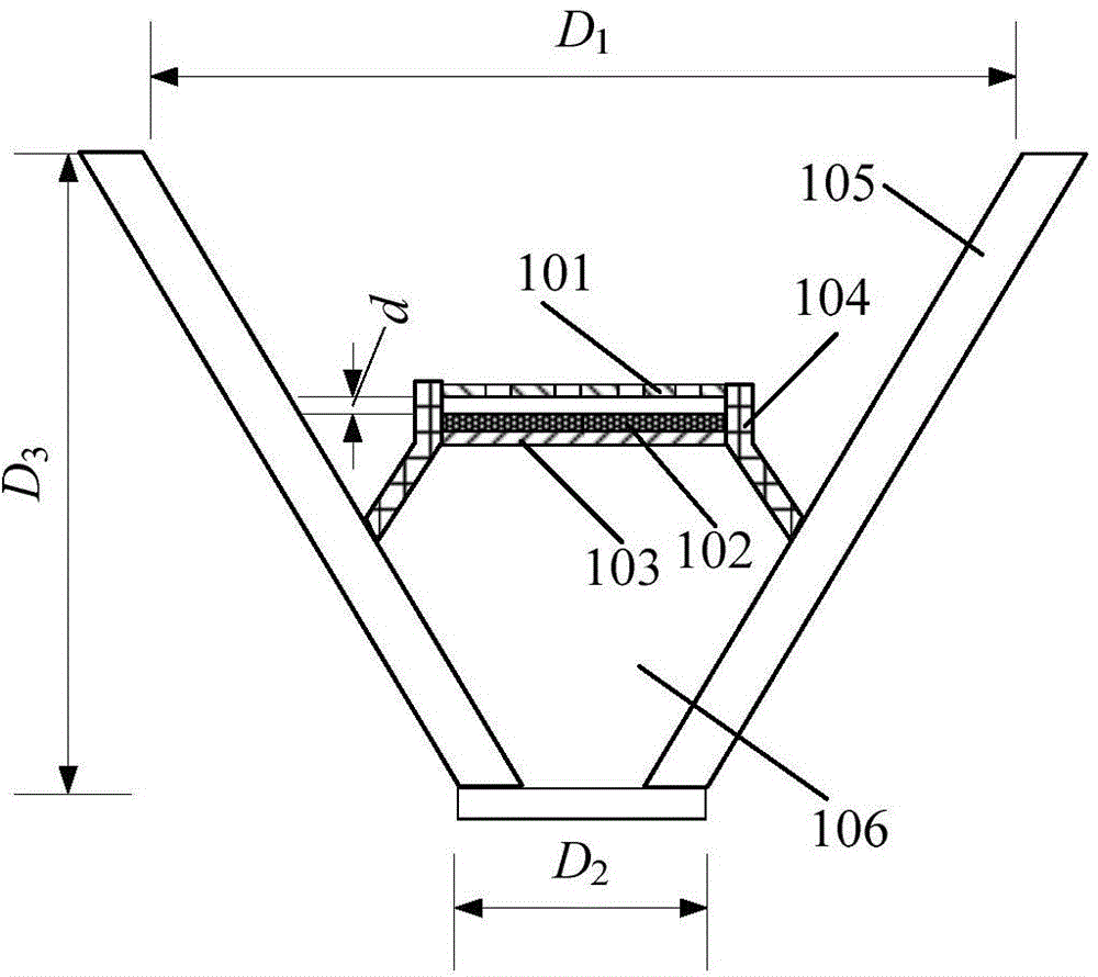
[0047] The generator utilizing sound energy of the present embodiment, see figure 1 , including an acoustic resonant cavity and a triboelectric nano-power generation component, wherein the acoustic resonant cavity 105 is a conical shell-shaped cavity structure with an opening, and the inner cavity is in the shape of a truncated cone, see figure 1 , the longitudinal section of the acoustic resonant cavity is inverted trapezoid; The triboelectric nano-power generation component includes two thin films facing each other, see figure 1 , the edge of the triboelectric nano-power generation component is fixed to the inner wall of the resonant cavity 105 through the support structure, including the first electrode layer 101, the second electrode layer 103 and the friction layer 102, wherein the lower surface of the first electrode layer 101 and the friction layer 102 The upper surfaces are arranged face to face, and the lower surface of the friction layer 102 is in contact with the s...
Embodiment 2
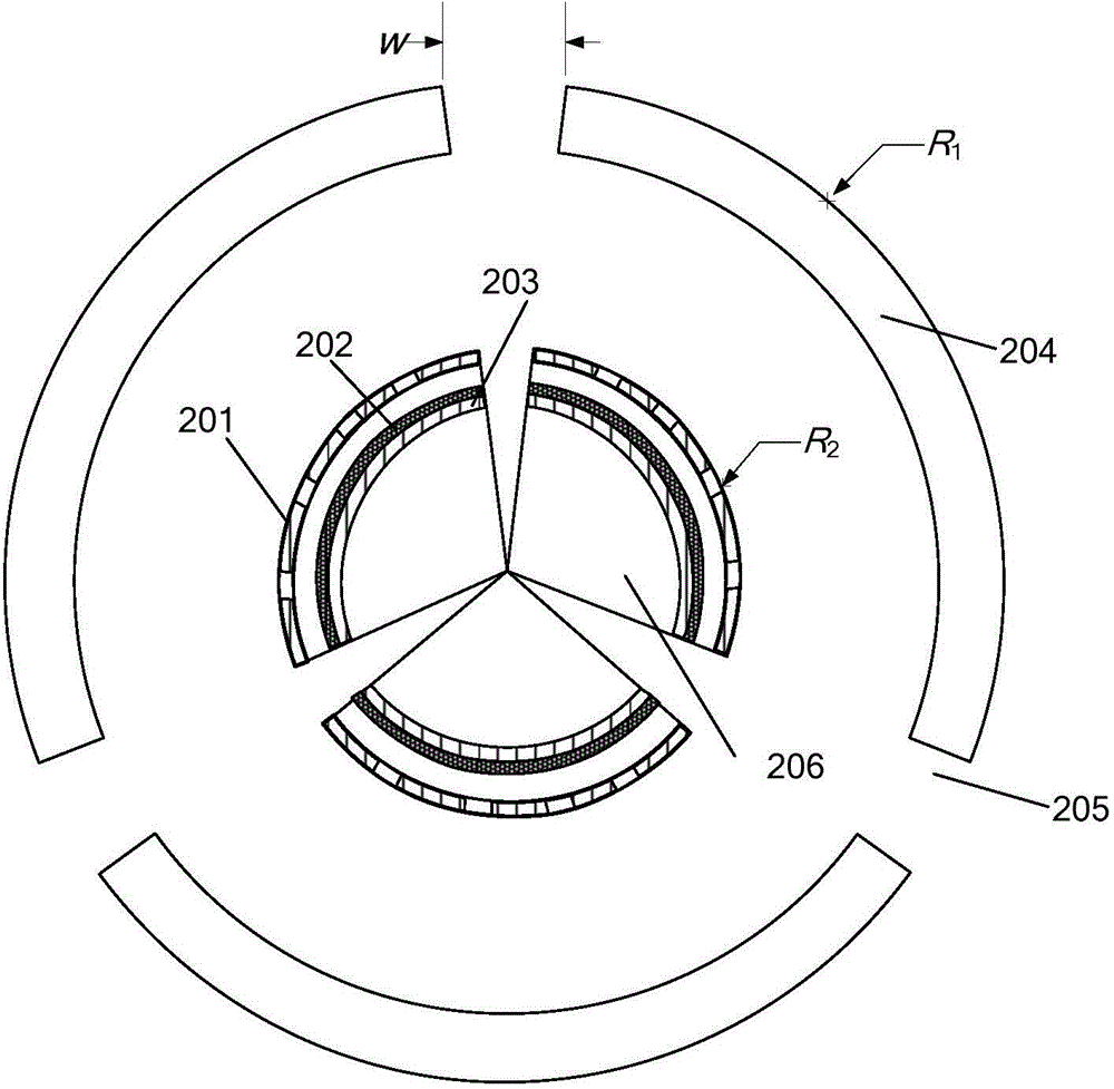
[0062] The generator utilizing sound energy of the present embodiment, see figure 2 , including an acoustic resonant cavity and at least one triboelectric nano-power generating component, wherein the outer wall of the acoustic resonant cavity 204 has at least one opening 205 , and all triboelectric nano-generating components are located in the cavity of the acoustic resonant cavity 204 . The opening 205 is a slit on the outer wall of the cylindrical shell, and the opening of the slit is square, circular or elliptical, which facilitates sound waves entering the acoustic resonance cavity 204 of the cylindrical shell. The structure of the triboelectric nano power generation component is basically the same as that in Embodiment 1, the only difference is that the first electrode layer 201, the second electrode layer 203 and the friction layer 202 of the triboelectric nano power generation component are not fixed to the outer wall of the acoustic resonance cavity 204, Instead, the ...
Embodiment 3
[0070] In Embodiment 1 and Embodiment 2, the greater the sound pressure of the standing wave is, the greater the oscillation amplitude of the elastic film formed by the friction layer and the second electrode layer in the triboelectric nano-power generation component is, and the higher the generated voltage is, the voltage and sound pressure In direct proportion, so as to realize acoustic sensing while collecting sound energy. The size, structure and opening diameter of the acoustic resonator jointly determine the frequency of the response to the sound wave, and the response of the generator to the sound frequency can be adjusted by adjusting the parameters of the acoustic resonator. The position of the triboelectric nanogenerating components (especially the elastic membrane) in the acoustic cavity determines the energy absorbed by the generator at the fundamental frequency or the double frequency sound wave. Therefore, the generator for collecting sound energy of the present ...
PUM
| Property | Measurement | Unit |
|---|---|---|
| Thickness | aaaaa | aaaaa |
| Thickness | aaaaa | aaaaa |
Abstract
Description
Claims
Application Information
 - R&D
- Intellectual Property
- Life Sciences
- Materials
- Tech Scout
- Unparalleled Data Quality
- Higher Quality Content
- 60% Fewer Hallucinations
Browse by: Latest US Patents, China's latest patents, Technical Efficacy Thesaurus, Application Domain, Technology Topic, Popular Technical Reports.
© 2025 PatSnap. All rights reserved.Legal|Privacy policy|Modern Slavery Act Transparency Statement|Sitemap|About US| Contact US: help@patsnap.com