Portal machining center combination for large part machining

A technology for processing centers and large parts, applied in metal processing equipment, metal processing machinery parts, manufacturing tools, etc., can solve the problems of incomplete cleaning of iron filings, affecting processing efficiency, inconvenient disassembly and assembly, etc., and achieves easy processing and production , high chip removal efficiency and long service life

Inactive Publication Date: 2015-08-19
CHONGQING MASITER PRECISION MACHINERY
View PDF8 Cites 5 Cited by
  • Summary
  • Abstract
  • Description
  • Claims
  • Application Information

AI Technical Summary

Problems solved by technology

The existing chip removal device is not only complex in structure, inconvenient to disassemble, but also not thorough in cleaning iron filings, and often requires manual secondary cleaning, which will affect the efficiency of processing

Method used


Image

  • Portal machining center combination for large part machining
  • Portal machining center combination for large part machining
  • Portal machining center combination for large part machining

Examples


Embodiment Construction

[0029] Below in conjunction with accompanying drawing and embodiment the present invention will be further described:

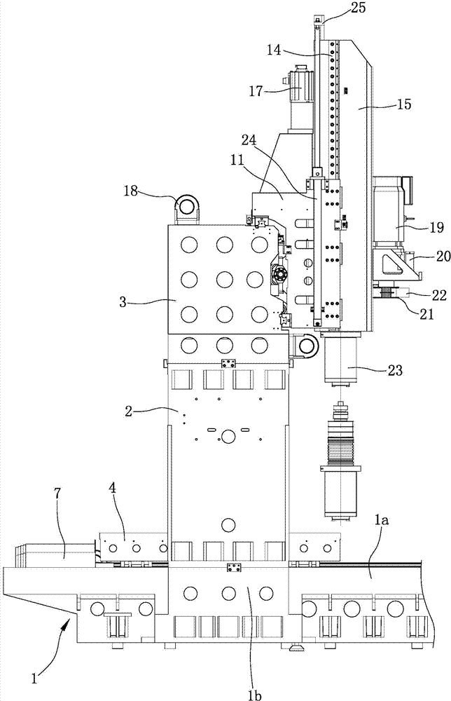
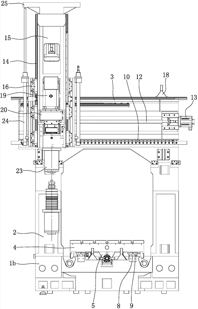
[0030] Such as figure 1 , figure 2 , Figure 4 , Figure 5 As shown, a rectangular support platform 1a is integrally formed on the top of the base 1, and the left and right sides of the top of the support platform 1a are symmetrically provided with chip removal grooves 1c, and the chip removal grooves 1c extend along the front and rear directions. It is "V" shape, and the front end of the chip removal groove 1c penetrates to the front end surface of the support table 1a. A spiral chip conveyor 26 is installed in each chip flute 1c. The spiral chip conveyor 26 is a prior art, and its structure will not be repeated here. During the operation of the screw chip conveyor 26, the iron chips in the chip removal groove 1c can be conveyed from the back to the front.

[0031] Such as Figure 4 , Figure 5 As shown, a support 1b is symmetrically arranged on the ...


PUM


Abstract

The invention discloses a portal machining center combination for large part machining. A support (1b) is a square frame body. An X-axis nut base (5) at the bottom of a working table (4) is in screw-thread fit with an X-axis lead screw (6). Nitrogen balancing cylinders (24) are symmetrically arranged on the left side and the right side of a Y-axis slide base (11). Cylinder bodies of the nitrogen balancing cylinders (24) are fixed to the Y-axis slide base (11). An output shaft of a main shaft motor (19) is connected with the input end of a gearbox (20). An output shaft of the gearbox (20) is sleeved with a driving wheel (21). The driving wheel (21) is connected with a driven wheel of a main shaft (23) through a belt (22). The movement in each axial direction is achieved through the large-torque motor and a screw-nut pair, complex profiles can be machined, high-speed cutting can be achieved, the low-speed large-torque cutting can be achieved as well, the nitrogen balancing cylinders are used for balancing the gravity of the main shaft box, and the stability of the Z-axis movement is ensured.

Description

technical field [0001] The invention belongs to the technical field of machine tools, and in particular relates to a gantry machining center assembly used for processing large parts. Background technique [0002] CNC machining center is a high-efficiency automatic machine tool suitable for processing complex parts composed of mechanical equipment and numerical control system. CNC machining centers are currently one of the most productive and widely used CNC machine tools in the world. Its comprehensive processing ability is strong, and the workpiece can complete more processing content after one clamping, and the processing accuracy is high. For batch workpieces with medium processing difficulty, its efficiency is 5 to 10 times that of ordinary equipment, especially it can complete The processing that cannot be completed by ordinary equipment is more suitable for single-piece processing with complex shapes and high precision requirements or small and medium-sized batches of...

Claims


Application Information

Patent Timeline
Patent Type & Authority Applications(China)
IPC IPC(8): B23Q5/40B23Q11/00
CPCB23Q5/402B23Q11/0042
Inventor 杨勇
Owner CHONGQING MASITER PRECISION MACHINERY
Why Eureka
Try Eureka