In situ pressure loading device for neutron small-angle scattering

A small-angle scattering and loading device technology, which is applied in the direction of applying stable tension/pressure to test the strength of materials, can solve the problems of small thickness and size, and achieve reliable performance, simple structure, and high measurement accuracy.

Inactive Publication Date: 2015-08-19
INST OF NUCLEAR PHYSICS & CHEM CHINA ACADEMY OF
View PDF4 Cites 13 Cited by
  • Summary
  • Abstract
  • Description
  • Claims
  • Application Information

AI Technical Summary

Problems solved by technology

In view of the different principles of neutron small-angle scattering technology and neutron diffraction technology, neutron small-angle scattering measurement requires neutron beam to pass through the sample directly, so the thickness of the sample in the dire

Method used


Image

  • In situ pressure loading device for neutron small-angle scattering
  • In situ pressure loading device for neutron small-angle scattering
  • In situ pressure loading device for neutron small-angle scattering

Examples


Embodiment 1

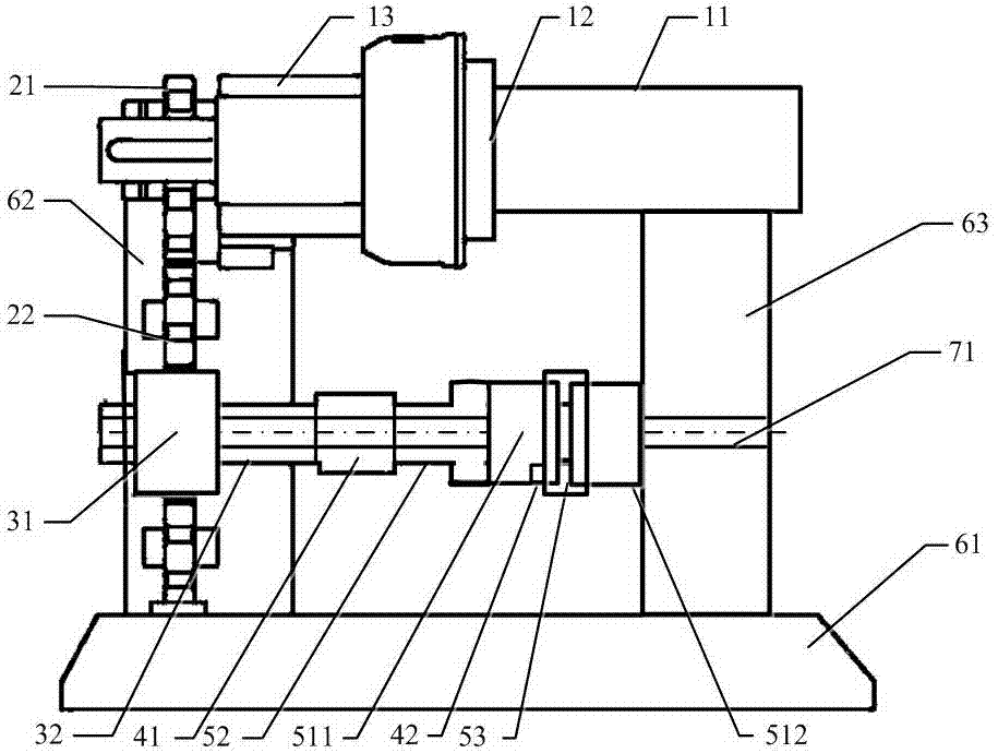
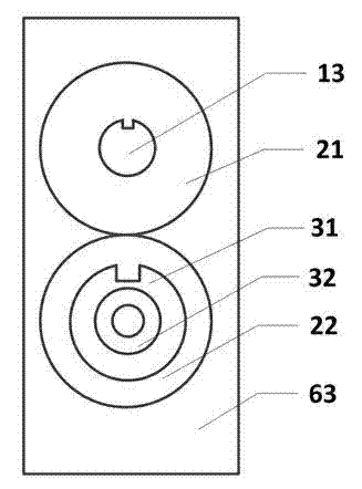
[0027] figure 1 It is a structural schematic diagram of the in-situ pressure loading device for small-angle neutron scattering of the present invention, figure 2 It is the left view of the in-situ pressure loading device for small-angle neutron scattering of the present invention, image 3 It is a schematic structural diagram of the mobile end fixture in the present invention, Figure 4 It is a structural schematic diagram of the fixed end clamp in the present invention, Figure 5 It is a schematic structural diagram of the sample cladding in the present invention. exist Figure 1 to Figure 5 Among them, the in-situ pressure loading device for neutron small-angle scattering of the present invention includes a power drive assembly, a transmission gear assembly, a ball screw assembly, a high-precision measurement assembly, a fixture assembly, a fixed frame base assembly and a shielding layer.

[0028]The power drive assembly includes a servo motor 11 , an encoder 12 and a r...

Embodiment 2

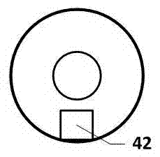
[0037] The structure of this embodiment is the same as that of Embodiment 1, except that the mechanical sensor 41 in the high-precision measurement component has a hollow inner diameter of 18mm, a measurement range of 0-5 kN, and a measurement accuracy of 0.5%; the non-contact displacement sensor 42 Replace it with a high-precision capacitive displacement sensor. The measurement accuracy of the capacitive displacement sensor is 0.01um, and the measurement range is 0~0.2mm. The capacitive displacement sensor includes a first capacitor plate and a second capacitor plate. The first capacitor plate is installed on the The lower end of the fixture at the movable end, and the second capacitor plate is installed at the lower end of the fixture at the fixed end. The lower ends of the movable end fixture 511 and the fixed end fixture 512 are respectively provided with fixed installation grooves matching the first capacitor plate and the second capacitor plate. The sample enclosure 53, ...


PUM


Abstract

The invention provides an in situ pressure loading device for neutron small-angle scattering. The in situ pressure loading device can conduct pressure loading for tested samples in the neutron beam direction and control stress and strain of the samples. The in situ pressure loading device comprises a power drive assembly, a transmission gear assembly, a ball screw assembly, a high-accuracy measurement assembly, a clamp assembly, a fixed machine frame base assembly and a shielding layer. The in situ pressure loading device is characterized in that a plurality of assemblies, which are of hollow structures, on a neutron beam line allow direct passing of neutrons, and a clamp is made of sapphire materials with high neutron transmittance, so as to achieve the pressure loading of the samples in the neutron beam direction. The in situ pressure loading device is matched with a neutron small-angle scattering spectrometer for use, conducts in situ detection on the microscopic deformation, damage and break processes of the tested samples in the mechanical use environment, and provides an effective and reliable means for study on further disclosure of the mechanical property and the damage and break mechanism of materials.

Description

technical field [0001] The invention belongs to the technical field of environmental loading in neutron small-angle scattering applications, and in particular relates to an in-situ pressure loading device for neutron small-angle scattering. The invention is used together with a small-angle neutron scattering spectrometer, and can detect the microscopic deformation, loss and destruction process of thin slice samples in a mechanical service environment on-line, which is helpful for the research on the mechanical properties and loss mechanism of materials. Background technique [0002] Neutron small-angle scattering technology has non-destructive detection and deep penetration characteristics, and is an effective method for studying the internal microstructure information of materials such as the precipitated phase of metals, the configuration of polymers and biomolecules, and dopants inside materials. The process of using neutron small-angle scattering technology to study the ...

Claims


Application Information

Patent Timeline
IPC IPC(8): G01N3/16
Inventor 庞蓓蓓孙光爱席志国王云张莹闫冠云龚建崔元平张洁田强曾军
Owner INST OF NUCLEAR PHYSICS & CHEM CHINA ACADEMY OF
Why Eureka
Try Eureka