Resonant cavity interior laser breakdown spectrum detection device

A laser breakdown spectrum and detection device technology, applied in the field of spectrum measurement, to achieve the effect of easy ionization and high breakdown power

Inactive Publication Date: 2015-08-19
NANJING INST OF ADVANCED LASER TECH
View PDF5 Cites 1 Cited by
  • Summary
  • Abstract
  • Description
  • Claims
  • Application Information

AI Technical Summary

Problems solved by technology

[0003] The current laser-induced breakdown spectroscopy requires high laser power. How to effectively increase the

Method used


Image

  • Resonant cavity interior laser breakdown spectrum detection device
  • Resonant cavity interior laser breakdown spectrum detection device
  • Resonant cavity interior laser breakdown spectrum detection device

Examples


Embodiment 1

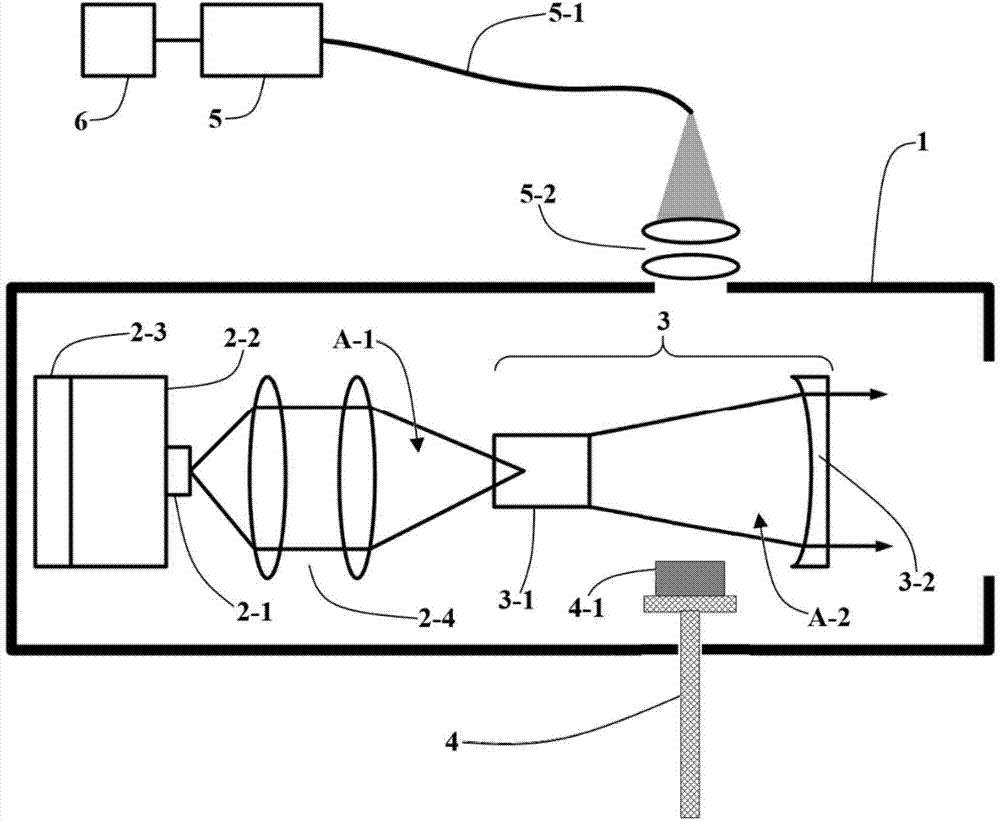
[0030] Such as figure 1 Shown is the basic structure diagram of this embodiment.

[0031] Inside the housing 1 is the structure of a Nd:YAG solid-state laser. A laser diode 2-1 is placed on a radiator 2-2 and a thermoelectric cooler (Thermoelectric Cooler, TE) 2-3. The pumping light A- 1 A group of concentrating devices 2-4 focus on the Nd:YAG crystal rod 3-1; the laser diode 2-1 emits laser light of about 810nm, and the Nd:YAG crystal rod 3-1 is near the end face of the laser diode 2-1 Coated with a film with high transparency to 810nm and high reflection to 1064nm, the rear cavity mirror as the output mirror is a concave mirror 3-2 with a radius of curvature of 5cm, and the concave mirror 3-2 is coated with a For a film with a reflectivity of 95% at 1064nm, the output mirror is a partial reflection mirror at this time; the output mirror and the Nd:YAG crystal rod 3-1 form a resonant cavity 3 . Usually the light intensity in the laser resonator is more than 10 times of the ...

Embodiment 2

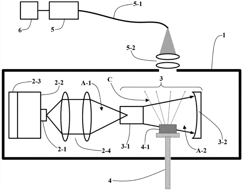
[0034] Such as image 3 As shown, the difference between this embodiment and embodiment 1 is that the end of the output mirror near the laser diode 2-1 is coated with a film with a reflectivity of 100% to 1064nm, and the output mirror is a total reflection mirror, so compared to embodiment 1 Said intracavity laser has higher power.

Embodiment 3

[0036] The laser light source of this embodiment uses CO with a wavelength of 10.6um 2 pulsed lasers, such as Figure 4 As shown, the resonant cavity 3 is an F-P cavity formed by a first plane mirror 3-3 and a second plane mirror 3-4 opposite on both sides, and the reflectivity of the opposite face of the two plane mirrors to the 10.6um wavelength incident light B-1 is 99.9%. Change the cavity length by adjusting the distance between the two plane mirrors, when the cavity satisfies the resonance condition u N =(c / 2L)*(N+θ / π), where u N is the interval of the longitudinal mode on the frequency coordinate, c is the speed of light, L is the length of the cavity, N is a natural number, θ is the phase change after the light wave is reflected once, the incident light B-1 resonates in the resonant cavity 3, at this time the cavity The standing wave intensity reaches the maximum, and the light intensity of the oscillating light B-3 is at least 10 times the light intensity of the inp...


PUM


Abstract

The invention relates to a resonant cavity interior breakdown spectrum detection device. The resonant cavity interior breakdown spectrum detection device comprises a laser light source, a spectrum analysis unit, a resonant cavity and a movable sample platform, wherein the spectrum analysis unit comprises a main machine and a spectrograph, and the resonant cavity is composed of a front cavity mirror and a second cavity mirror. The resonant cavity interior breakdown spectrum detection device is characterized in that the resonant cavity, such as a resonant cavity in a solid-state laser device, is utilized, or an F-P type resonant cavity is directly used for forming a resonance state inside the resonant cavity by virtue of lasers, so that the relatively strong light intensity is produced, a to-be-detected substance is moved to a position with strong light in the resonant cavity, the to-be-detected substance absorbs heat and produces plasma, the plasma transmits light rays, and the light rays are analyzed by the spectrograph, so that ingredients and the content of the to-be-detected substance are obtained. The resonant cavity interior breakdown spectrum detection device has the advantages that the used laser has relatively high breakdown power, so that the to-be-detected substance can be ionized relatively easily, and a relatively large quantity of substance ingredients can be analyzed; and the light intensity inside the cavity is at least 10 times stronger than that outside the cavity, so that the power of the laser can be at least reduced by 10 times and more under the condition of the same effect of the light intensity inside and outside the cavity.

Description

technical field [0001] The invention relates to the technical field of spectrum measurement, in particular to a laser breakdown spectrum detection device in a resonant cavity. Background technique [0002] Laser-induced breakdown spectroscopy is a laser ablation spectral analysis method. The laser is focused on the sample to be tested (which can be solid, liquid or gas) through a lens. When the energy density of the laser is greater than the breakdown threshold of the sample to be tested, the Plasma will be generated locally. The local energy density and temperature of this plasma are very high. Use a spectrometer to collect the signal of the emission line generated on the plasma surface of the sample to be tested, and then quantitatively analyze the substances inside according to the intensity of the emission line. concentration. [0003] The current laser-induced breakdown spectroscopy requires high laser power. How to effectively increase the light intensity under the co...

Claims


Application Information

Patent Timeline
IPC IPC(8): G01N21/63G01N21/01
Inventor 王欢
Owner NANJING INST OF ADVANCED LASER TECH
Why Eureka
Try Eureka