Supercharge Your Innovation With Domain-Expert AI Agents!

Surface-coated cutting tool with excellent abnormal damage resistance and wear resistance

A cutting tool and surface coating technology, applied in the field of surface coating cutting tools, can solve the problems of reducing chipping, short tool life, insufficient wear resistance, etc., and achieve the effect of improving defect resistance

Active Publication Date: 2018-09-14
MITSUBISHI MATERIALS CORP
View PDF8 Cites 0 Cited by
  • Summary
  • Abstract
  • Description
  • Claims
  • Application Information

AI Technical Summary

Problems solved by technology

[0009] Although the conventional coated tool described in the above-mentioned Patent Document 1 exhibits excellent chipping resistance and wear resistance in continuous cutting and interrupted cutting of carbon steel, it cannot be said to be suitable for high-speed cutting of high-hardness steel. Both chipping resistance and abrasion resistance are sufficient
[0010] In addition, the conventional coated tool described in the above-mentioned Patent Document 2 shows excellent chipping resistance in high-speed interrupted cutting of bearing steel and chrome steel, but it is not yet sufficient in terms of wear resistance.
[0011] In short, the existing coated tools cannot ensure excellent wear resistance while reducing the occurrence of abnormal damage such as chipping and chipping in high-speed continuous cutting and high-speed interrupted cutting of high-hardness steel, so the tool life is short. The problem

Method used


Image

  • Surface-coated cutting tool with excellent abnormal damage resistance and wear resistance
  • Surface-coated cutting tool with excellent abnormal damage resistance and wear resistance
  • Surface-coated cutting tool with excellent abnormal damage resistance and wear resistance

Examples


Embodiment 1

[0081] Production of the tool base:

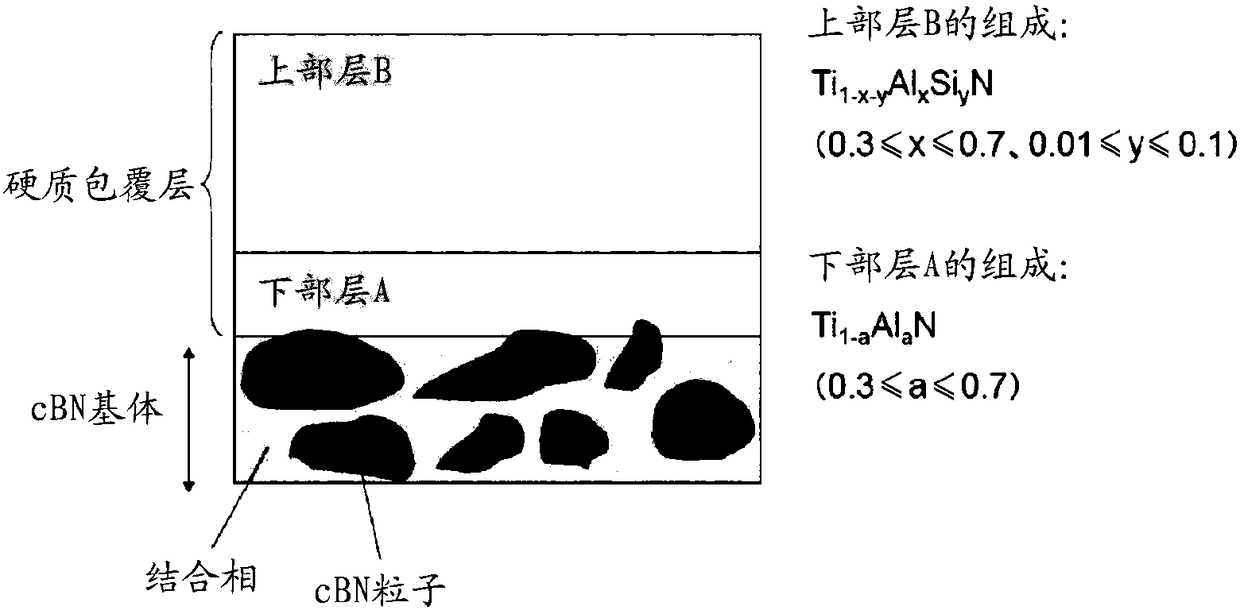
[0082] As the raw material powder, prepare cBN particles having an average particle diameter of 0.5 to 4.0 μm as the raw material powder for forming a hard phase, and prepare TiN powder, TiC powder, and TiCN powder each having an average particle diameter in the range of 0.3 to 0.9 μm. , Al powder, AlN powder, Al 2 o 3 The powder is used as a raw material powder for forming a binder phase.

[0083] The compounding ratio shown in Table 1 was compounded so that the content ratio of the cBN particle powder when the total amount of some of these raw material powders and cBN particle powder was 100 volume % became 40-70 volume %.

[0084] Next, wet-mix the raw material powder with a ball mill for 72 hours, and after drying, use a press to press 1 MPa to extrude according to the size of diameter: 50mm×thickness: 1.5mm, and then press the molded body under the pressure: In a vacuum atmosphere below 1 Pa, heat treatment is performed at 1000°C f...


PUM

PropertyMeasurementUnit
particle sizeaaaaaaaaaa

Abstract

The present invention provides a surface coating cutting tool which is difficult to fracture, damage and peel when being used for the high speed cutting processing of a glass hard steel having a high load cutting condition, and shows an excellent wear resistance for a long time. A lower layer A and an upper layer B of which the average total thickness is between 1.5 micrometers and 4.0 micrometers wrap on a tool matrix of the surface coating cutting tool formed by a cBN sintering body, the lower layer A is composed of Til-alpha AlaN wherein the atomic ratio alpha is not less than 0.3 and not more than 0.7, and the upper layer is composed of Til-x-yAlxSiyN, wherein the atomic ratio x is not less than 0.3 and not more than 0.7, and the y is not less than 0.01 and not more than 0.1. The residual stress of the lower layer A at the back blade surface of the surface coating cutting tool is set as omega A (GPa), and the overall residual stress of a hard wrapping layer is set as omega T (GPa), and the relations are satisfied: omega A<omega T, -7.0<=omega A<=-1.0, -4.0<=omega T<=-0.5, the absolute value (omegaA-omega T<4.0. Further, the average thickness of the lower layer A is set as tA, the average thickness of the upper layer B is set as tB, and the relation is satisified: 4<=tB / tA<=9, and the average grain diameter of the lower layer A is less than 0.1 micrometers.

Description

technical field [0001] The present invention relates to a surface-coated cutting tool (hereinafter referred to as a coated tool) which has excellent abnormal damage resistance and wear resistance due to a hard coating layer, so that even when used in Hardened steel and other high-hardness steels are hard to chip and chip when high-speed cutting, and have shown excellent cutting performance for a long time. Background technique [0002] In general, cladding tools include: inserts that are detachably attached to the front end of a turning tool for turning or flat-cutting workpieces such as various steels or cast iron; Drills or micro-drills; and integral end mills used in surface cutting, groove processing, or step processing of workpieces, etc., and there are known inserts that are detachably installed and similar to the integral end mills. Cutting insert type end mills, etc. [0003] The present invention relates to a cBN sintered body cutting tool with cubic boron nitride...

Claims


Application Information

Patent Timeline
Patent Type & Authority Patents(China)
IPC IPC(8): B23B27/14C04B35/5831C04B41/89
CPCC23C14/0641C23C30/005
Inventor 佐藤峻仙北屋和明高桥正训
Owner MITSUBISHI MATERIALS CORP
Features
  • R&D
  • Intellectual Property
  • Life Sciences
  • Materials
  • Tech Scout
  • Unparalleled Data Quality
  • Higher Quality Content
  • 60% Fewer Hallucinations
Learn More