Bidirectional control drive circuit applied to energy storage inverter

An energy storage inverter and drive circuit technology, applied in electrical components, output power conversion devices, AC power input conversion to DC power output and other directions, can solve problems such as analog synchronous rectification chip control, affecting normal work, etc.

Active Publication Date: 2016-10-12
GOODWE TECHNOLOGIES CO LTD
View PDF8 Cites 0 Cited by
  • Summary
  • Abstract
  • Description
  • Claims
  • Application Information

AI Technical Summary

Problems solved by technology

In the energy storage inverter, the energy needs to be controlled bidirectionally, and both the primary and secondary sides need to be driven and controlled. Therefore, the secondary side cannot be simply controlled by a dedicated analog synchronous rectification chip. Otherwise, when the energy flows in the opposite direction, the drive controlled by the synchronous rectification chip will Affect normal work

Method used


Image

  • Bidirectional control drive circuit applied to energy storage inverter

Examples


Embodiment 1

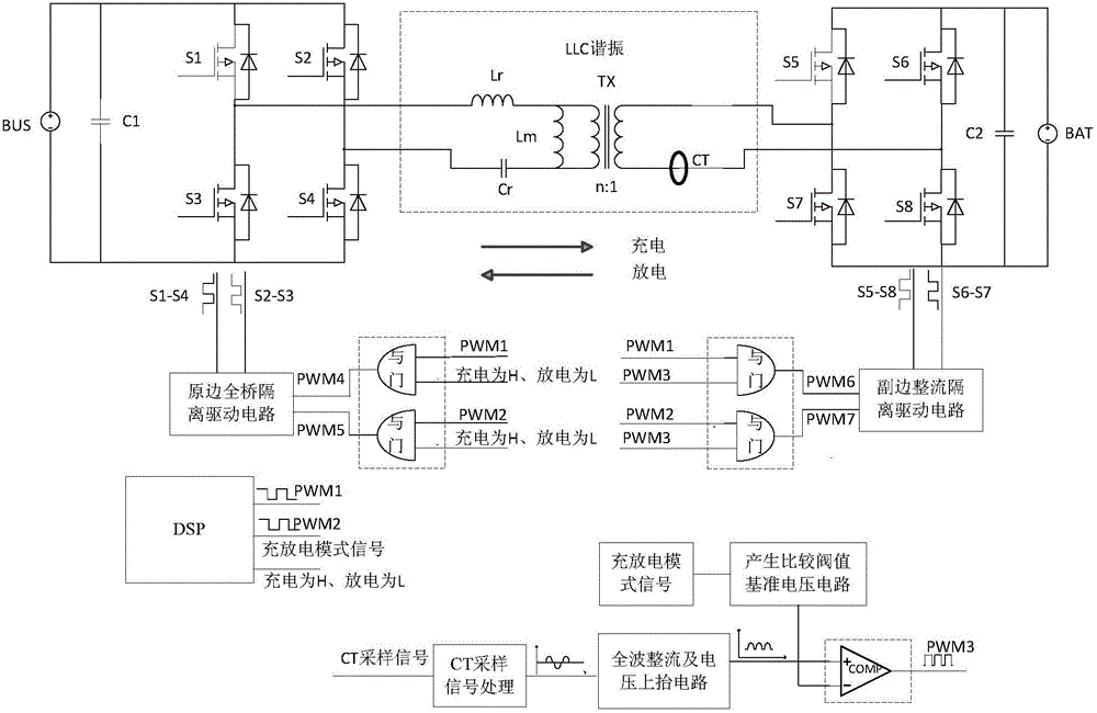
[0018] Embodiment one: as attached figure 1 As shown, the energy storage inverter includes a primary side and a secondary side connected through an LLC resonant circuit, wherein the primary side includes the primary side signal source BUS and the primary side connected between the primary side signal source BUS and the primary side of the LLC resonant circuit The full bridge circuit, the secondary side includes a secondary side signal source BAT and a secondary side full bridge circuit connected between the secondary side of the LLC resonant circuit and the secondary side signal source BAT. The full-bridge circuit on the primary side and the full-bridge circuit on the secondary side are composed of four field effect transistors S1-S4 and S5-S8 respectively to form a full-bridge structure. The LLC resonant circuit includes a transformer Tx and a resonant capacitor Cr and a resonant inductor Lr arranged on its primary side. When charging, energy flows from the primary side to t...


PUM


Abstract

The invention relates to a bidirectional control driving circuit applied to an energy storage inverter. The bidirectional control driving circuit comprises a current sampler, a DSP module, a comparison threshold reference voltage generation circuit, a comparator and four AND gates. The DSP module generates a charge and discharge mode signal, a first driving signal and a second driving signal. The comparator compares a voltage signal obtained by the current sampler with a comparison threshold reference voltage signal generated by the comparison threshold reference voltage generation circuit and generates a third driving signal. The first driving signal, the second driving signal and the charge and discharge mode signal are respectively input into the first AND gate and the second AND gate, the first AND gate and the second AND gate respectively generate a fourth driving signal and a fifth driving signal, and the fourth driving signal and the fifth driving signal are sent to a primary side of the energy storage inverter. The first driving signal, the second driving signal and the third driving signal are respectively input into the third AND gate and the fourth AND gate, the third AND gate and the fourth AND gate respectively generate a sixth driving signal and a seventh driving signal, and the sixth driving signal and the seventh driving signal are sent to a secondary side of the energy storage inverter. According to the invention, bidirectional control of energy is realized, and the bidirectional control driving circuit is applicable to the energy storage inverter which is bidirectional in energy flow.

Description

technical field [0001] The invention belongs to the technical field of power electronic converters, and relates to a bidirectional control drive circuit suitable for energy storage inverters. Background technique [0002] In the ideal LLC circuit applied to the energy storage inverter, when the switching frequency fsw ≥ the resonant frequency fr, the synchronous rectification MOSFET on the secondary side can drive synchronous switching with the primary side; and in the case of fsw<fr, the rectification MOSFET on the secondary side The driver should be turned off before the end of the LrCr resonance, otherwise it will cause energy backflow, and even lead to resonance error and bombing. However, there are many parasitic parameters in the actual circuit that will affect the LLC resonance, especially the leakage inductance of the transformer cannot be accurately controlled, resulting in the resonant frequency fr=1 / 2π(Lr*Cr)^0.5 cannot be accurately controlled, so when the sec...

Claims


Application Information

Patent Timeline
Patent Type & Authority Patents(China)
IPC IPC(8): H02M7/797
Inventor 黄敏方刚许金韡
Owner GOODWE TECHNOLOGIES CO LTD
Why Eureka
Try Eureka