Polycrystalline silicon production method and device by pyrogenation of silane

A production device and technology for polysilicon, applied in chemical instruments and methods, silicon compounds, inorganic chemistry, etc., can solve the problems of dust control, high energy consumption of polysilicon, and achieve the effect of improving thermal efficiency

Active Publication Date: 2015-09-02
SHANGHAI JIAO TONG UNIV
View PDF8 Cites 5 Cited by
  • Summary
  • Abstract
  • Description
  • Claims
  • Application Information

AI Technical Summary

Problems solved by technology

[0009] In view of the above-mentioned defects of the prior art, the technical problem to be solved by the present invention is to provide a production device and method to solve the problems of high energy consumption and dust control in the polysilicon production process

Method used


Image

  • Polycrystalline silicon production method and device by pyrogenation of silane
  • Polycrystalline silicon production method and device by pyrogenation of silane
  • Polycrystalline silicon production method and device by pyrogenation of silane

Examples


Embodiment 1

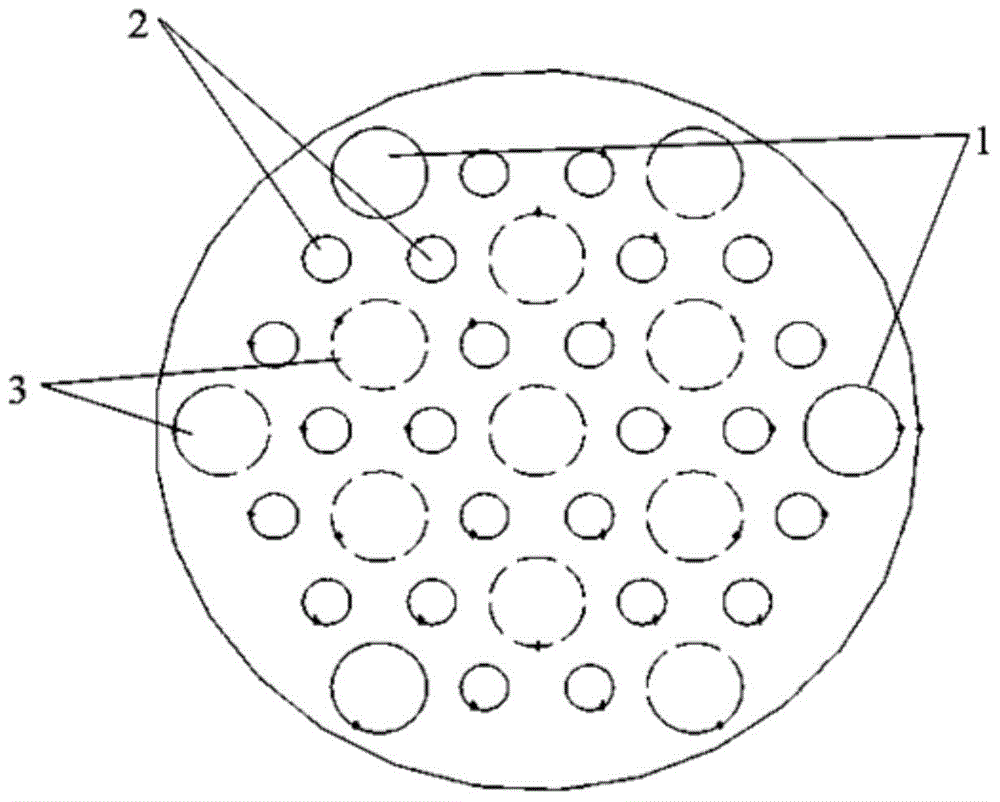
[0035] Example 1: A small bell jar reactor with 12 pairs of silicon rods, the center distance of the silicon rods is 180mm, the height of the silicon rods is 1200mm, the diameter of the guide tube is 160mm, and the height of the guide tube is 1000mm. The arrangement of the silicon rods and the guide tube is as follows image 3 As shown, six rectangular slit nozzles are opened on the side walls of the seven guide tubes in the central area, respectively facing the six silicon rods around them, and three slit nozzles are opened on the side walls of the three inlet guide tubes on the edge, facing respectively There are three silicon rods around, and three circular outlet guide tubes are evenly distributed on the edge. The slit nozzle width on the side wall of the inlet guide tube is 0.1mm, corresponding to the feed gas nozzle velocity of 2.8m / s.

[0036] The molar concentration of silane in the feed gas at a temperature of 350K is 2%, the emissivity of the outer surface of the poli...

Embodiment 2

[0037] Example 2: a medium-sized bell jar reactor with 30 pairs of silicon rods, the center distance of the silicon rods is 220mm, the height of the silicon rods is 2100mm, the diameter of the guide tube is 220mm, and the height of the guide tube is 2000mm. The arrangement of the silicon rods and the guide tube is as follows Figure 5 As shown, six rows of nozzles are opened on the side walls of the nineteen air guide tubes in the central area, respectively facing the six silicon rods around them, and four rows of nozzles are opened on the side walls of the twelve inlet guide tubes on the edge, facing the four surrounding silicon rods respectively. Silicon rods, six rectangular outlet guide tubes are evenly distributed on the edge, and each row of nozzles on the side wall of the inlet guide tube contains 10 uniformly distributed nozzle holes with a diameter of 1mm, corresponding to the feed gas nozzle velocity of 25.2m / s.

[0038]The molar concentration of silane in the feed ga...

Embodiment 3

[0039] Embodiment 3: a medium-sized bell jar reactor with 30 pairs of silicon rods, the arrangement of the silicon rods and the guide cylinder is referred to in Example 2, the difference is that the bell jar has an exhaust port, and the reaction tail gas is discharged from the top of the bell jar reactor. Each row of nozzles on the side wall of the air intake guide tube contains 20 circular nozzle holes with a diameter of 0.5-1.5 mm that gradually decrease from bottom to top, corresponding to the feed gas nozzle velocity of 15.8m / s.


PUM

PropertyMeasurementUnit
heightaaaaaaaaaa
heightaaaaaaaaaa
diameteraaaaaaaaaa

Abstract

The invention discloses a polycrystalline silicon production method and device by pyrogenation of silane. The production device comprises an immersion bell and a disc bottom plate, wherein a reaction region is formed by the immersion bell and the disc bottom plate; silicon rods are arranged hexagonally; a plurality of air inlet guide cylinders are arranged on the bottom plate; nozzles are formed on the side walls of the guide cylinders; raw material gas enters the reaction region from the nozzles and is directly sprayed to the surfaces of the carbon rods; reaction tail gas is exhausted from the top of an immersion bell reactor or enters an outlet guide cylinder to be discharged. In production by the device, low-temperature reaction gas is directly sprayed to the surfaces of the carbon rods where deposition reaction happens, so that the periphery of the high-temperature silicon rods is cooled. A severe synergistic effect is obtained for the heat and mass transfer; the guide cylinders among the silicon rods have low-temperature isolating effects; the raw material gas is pre-heated by radiation heat, so that the heat efficiency is improved and the effect of reducing the energy consumption is obtained.

Description

technical field [0001] The invention relates to a polysilicon production device, in particular to a production device for manufacturing polysilicon rods by utilizing silane decomposition. Background technique [0002] The manufacture of high-purity polysilicon usually uses a Siemens bell-shaped reactor. High-purity silicon-containing gas (trichlorosilane or silane gas) and hydrogen are injected upward from the nozzle of the bell chassis, and a chemical vapor phase occurs on the surface of the high-temperature silicon rod heated by electric current. Deposition (CVD) reaction. Two adjacent, parallel pairs of silicon rods are connected together to form an inverted U-shaped structure, and the two ends are respectively connected to the two poles of the power supply. The center distance of the silicon rods is greater than the maximum growth diameter of the silicon rods. The silicon rods in the reactor are mainly arranged in two ways (such as figure 1 ): The gas inlet and outlet ...

Claims


Application Information

Patent Timeline
Patent Type & Authority Applications(China)
IPC IPC(8): C01B33/027
Inventor 肖文德阎建民李学刚罗漫
Owner SHANGHAI JIAO TONG UNIV
Why Eureka
Try Eureka