Multi-machine system and synchronization method
A technology of multi-machine system and synchronization signal, applied in the field of multi-machine system, to achieve the effect of source synchronization function, simple hardware connection and good system stability
- Summary
- Abstract
- Description
- Claims
- Application Information
AI Technical Summary
Problems solved by technology
Method used
Image
Examples
Embodiment 1
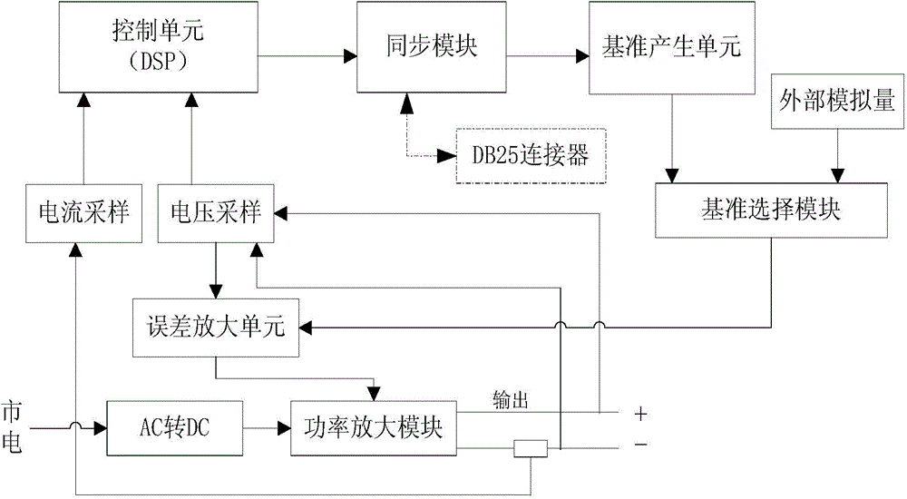
[0026] Such as figure 1 As shown, the first embodiment takes an AC and DC power supply as an example, including an AC-DC conversion module, a power amplification module, a reference generation unit, a voltage sampling unit, a current sampling unit, a control unit, an error amplification unit and a synchronization module. The AC-DC conversion module converts the commercial power into direct current as the direct current power input of the power amplifier module, and the power amplifier module amplifies the input signal and then outputs it. The voltage sampling unit and the current acquisition unit respectively collect the voltage and current at the output end of the power amplification module, convert it into a digital signal through the AD conversion module, and then transmit it to the control unit as the instantaneous value of the output voltage and output current, which are used to calculate the effective value of the voltage and the effective current Value, active power, re...
Embodiment 2
[0034] When multiple AC and DC power supplies are connected in parallel to form a single-phase AC power system, one of the power supplies is configured as a master, and the rest are configured as slaves. The synchronous trigger signal of the host comes from the DSP of the machine, the cycle synchronous signal is generated by the waveform reference after the waveform zero-crossing processing, the synchronous opening and closing signal comes from the host computer, and the system fault alarm signal comes from the host computer. The synchronization signal input end of the synchronization module of the slave machine is connected with the synchronization signal output end of the synchronization module of the master machine, and receives the synchronization signal sent by the master machine. When multiple machines are connected in parallel to form a single-phase power supply, the connection between the error amplifier unit and the power amplifier module of the slave machine is discon...
Embodiment 3
[0036]When at least two AC power supplies are connected to form a multi-phase AC power supply system, one of the power supplies is configured as a master, and the rest are configured as slaves; the synchronization trigger signal of the master comes from the local DSP, and the cycle synchronization signal is processed by the waveform reference through waveform zero-crossing Generated later, the synchronous opening and closing signal comes from the host computer, and the system failure alarm signal comes from the host computer. The synchronization signal input end of the synchronization module of the slave machine is connected with the synchronization signal output end of the synchronization module of the master machine, and receives the synchronization signal sent by the master machine.
[0037] Figure 4 The synchronous control flowchart for the multi-phase AC power system includes the following steps:
[0038] (1) Receive the synchronous opening signal;
[0039] (2) Master ...
PUM
 Abstract
Description
Claims
Application Information
 - R&D
- Intellectual Property
- Life Sciences
- Materials
- Tech Scout
- Unparalleled Data Quality
- Higher Quality Content
- 60% Fewer Hallucinations
Browse by: Latest US Patents, China's latest patents, Technical Efficacy Thesaurus, Application Domain, Technology Topic, Popular Technical Reports.
© 2025 PatSnap. All rights reserved.Legal|Privacy policy|Modern Slavery Act Transparency Statement|Sitemap|About US| Contact US: help@patsnap.com


