
Universal pulse width modulation method for multi-level inverter

A multi-level inverter, pulse width modulation technology, applied in the direction of AC motor control, control system, electrical components, etc., can solve problems such as electromagnetic interference, common mode voltage and common mode current interference, capacitor voltage imbalance, etc. Achieve the effect of improving safety and work performance, strong feasibility and effectiveness, good scalability and portability

Inactive Publication Date: 2015-09-02
CHANGAN UNIV
View PDF7 Cites 10 Cited by
  • Summary
  • Abstract
  • Description
  • Claims
  • Application Information

AI Technical Summary

Problems solved by technology

However, there are still some problems in the application of multi-level inverters that need to be further resolved: pulse width modulation technology implementation algorithm complex, large modulation technology calculation load, capacitor voltage imbalance on the DC side of the inverter, and the presence of common-mode voltage and Common mode current interference issues, etc.
[0004] In the existing multi-level inverter power supply technology, the common mode voltage problem will cause the motor shaft voltage, bearing current and induced electromagnetic interference. At present, relevant researchers have conducted a lot of research on this problem, but the current The solution techniques are more complex or computationally intensive

Method used


Image

  • Universal pulse width modulation method for multi-level inverter
  • Universal pulse width modulation method for multi-level inverter
  • Universal pulse width modulation method for multi-level inverter

Examples


Embodiment Construction

[0043] The present invention will be further described in detail below in conjunction with the drawings.

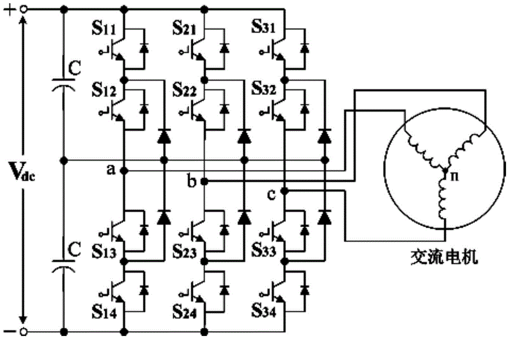
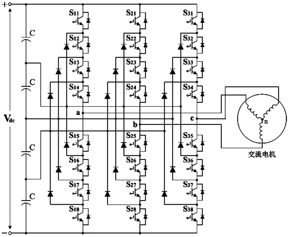
[0044] See figure 1 , 2, For odd-numbered multi-level inverters, such as three-level inverters, five-level inverters, seven-level inverters, etc., if the traditional space vector modulation method is used to achieve the synthesis of reference voltage vectors , The implemented algorithm is more complicated, and the conventional algorithm will cause the inverter output voltage to contain common mode voltage components, which greatly affects the inverter output performance. The present invention proposes a pulse width modulation technology that can effectively suppress common mode voltage components. Taking the traditional five-level inverter topology as an example, the inverter consists of three power switch bridge arms, a DC bus power supply and four It is composed of a voltage divider capacitor, and each bridge arm is composed of eight power switches and six clamping diodes...


PUM


Abstract

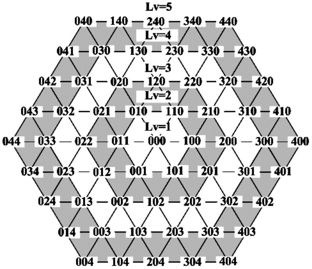
A universal pulse width modulation method for a multi-level inverter includes the following steps: a, carrying out per unit of reference input voltages; b, calculating a two-level space vector pulse width modulation duty ratio; c, calculating in which layer a reference voltage vector is on; d, performing vector reverse mapping; e, inhibiting common-mode voltages; and f, generating pulse-width modulated waves. A voltage vector switching time duty ratio of an inverter is calculated by a simple two-level space voltage vector modulation algorithm, then vector compression is performed on the duty ratio, a mapping relation based on the voltage vector and level is established, and multi-level voltage conversion can be effectively achieved through the series of conversion. Through level conversion, the voltage vector that has a common-mode voltage inhibition capability can be output easily and quickly, and a specific pulse width modulation output state is selected to prevent generation of common-mode voltages, thereby effectively inhibiting common-mode components included in output voltages of a multi-level inverter.

Description

Technical field [0001] The invention belongs to the technical field of power electronics, and relates to a general pulse width modulation method for a multi-level inverter. Background technique [0002] In recent years, inverter power supply technology has been widely used in the field of AC motor drive. The inverter can effectively achieve motor frequency conversion and amplitude modulation voltage control. For medium and high power transmission devices, such as electric locomotives and ship propulsion, compared with traditional two-level voltage source inverters, the application of multi-level inverters has many advantages: lower power switch stress, lower Inverter output voltage harmonic distortion, lower output voltage pulsation and less electromagnetic interference. Research on multilevel inverters pays more attention to three topological structures: series H-bridge multilevel inverters, neutral point clamped multilevel inverters and dual inverters based on open-phase AC mo...

Claims


Application Information

Patent Timeline
Patent Type & Authority Applications(China)
IPC IPC(8): H02M7/483H02M7/5387H02M1/12H02P27/08
CPCH02M7/487
Inventor 林海闫茂德陈金平周熙伟司利云李晓辉李杰李刚龚贤武
Owner CHANGAN UNIV
Learn More