Biomolecule measuring device
一种生物分子、测量装置的技术,应用在测量装置、生物化学清洗装置、酶学/微生物学装置等方向,能够解决分析时间增大等问题,达到降低测定噪声的效果
- Summary
- Abstract
- Description
- Claims
- Application Information
AI Technical Summary
Problems solved by technology
Method used
Image

Examples
Embodiment approach 1
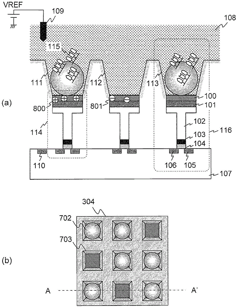
[0062] Embodiments of the present invention will be described below using the drawings. Here, an ISFET is used as a semiconductor sensor, and a DNA sequencer for determining the sequence of DNA is used as an example of a biomolecule measuring device. However, the application target of the present invention is not limited to a DNA sequencer, and can be widely used in electrical A system for measuring the reaction products of biomolecules. An ISFET can detect various ions by appropriately selecting an ion-sensitive membrane, and therefore, for example, the present invention can be applied to a device for measuring biomolecules that change sodium ions and potassium ions. In addition, in all the drawings for explaining the embodiment, in principle, the same reference numerals are attached to the same components, and their repeated descriptions are omitted.
[0063] refer again figure 1 . The ISFET array 304 has a plurality of wells 703 arranged two-dimensionally, and the ion-se...
Embodiment approach 2
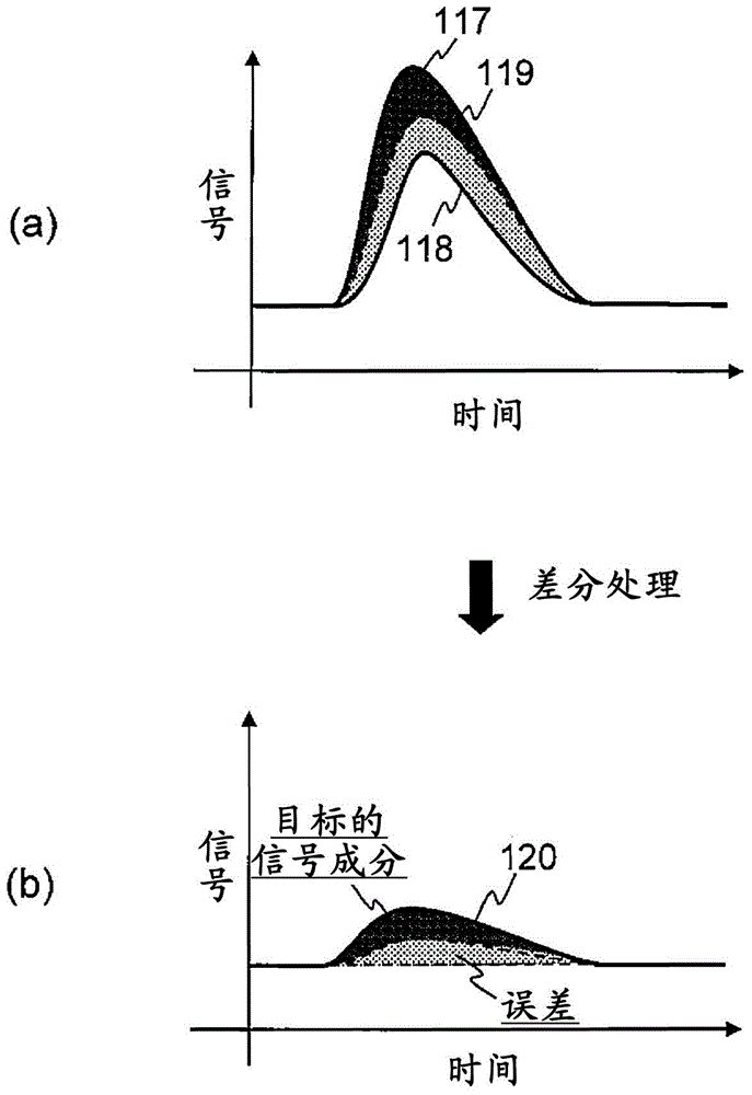
[0114] In Embodiment 1, it was described that the drift / offset component 1301 and the background 1300 are subtracted from the signal waveform detected by the ISFET 114 by calculation, and only the extended signal 1302 is taken out. In Embodiment 2 of the present invention, another configuration example in which the drift / offset component 1301 and the background 1300 are subtracted will be described.
[0115] Figure 15 It is a circuit diagram extracting one cell and its peripheral circuits on the ISFET array chip 1002 included in the biomolecule measurement device according to the second embodiment. Although not shown, it is actually the same as Figure 9 Likewise, there are a plurality of row selection lines WL, source lines SL, data lines DLA and DLB. Regarding the ISFET 114, only the ion sensitive film 100 and the floating gate 102 are schematically shown, and the protective film 101 is omitted.
[0116] In Embodiment 2, the floating gate 102 is connected to a constant v...
Embodiment approach 3
[0132] In Embodiments 1 and 2, a configuration example in which the signal quality of the ISFET 114 is improved by removing the drift / offset component 1301 and the background component 1300 has been described. In Embodiment 3 of the present invention, a configuration example in which the signal quality of ISFET 114 is improved by other means will be described.
[0133] Figure 18 It is a functional block diagram of the biomolecule measuring device according to the third embodiment. The biomolecule measuring device according to the third embodiment includes an excess solution removing device 315 in addition to the configuration described in the second embodiment. The other configurations are the same as in Embodiment 2, so the following description will focus on differences.
[0134] The excess solution removing device 315 is a device for removing the reagent solution existing outside the well 703 and is controlled by the controller 312 . Residual solution removal device 315...
PUM
 Abstract
Description
Claims
Application Information
 - R&D
- Intellectual Property
- Life Sciences
- Materials
- Tech Scout
- Unparalleled Data Quality
- Higher Quality Content
- 60% Fewer Hallucinations
Browse by: Latest US Patents, China's latest patents, Technical Efficacy Thesaurus, Application Domain, Technology Topic, Popular Technical Reports.
© 2025 PatSnap. All rights reserved.Legal|Privacy policy|Modern Slavery Act Transparency Statement|Sitemap|About US| Contact US: help@patsnap.com