
Novel self-chip-removal machine tool

A new type of self-discharging technology, applied in the field of machine tools, can solve the problems affecting the machining accuracy of the drill bit and the machining quality of the workpiece, and achieve the effect of improving chip efficiency, stable work and smooth chip removal.

Inactive Publication Date: 2015-09-09
蚌埠市金林数控机床制造有限公司
View PDF5 Cites 14 Cited by
  • Summary
  • Abstract
  • Description
  • Claims
  • Application Information

AI Technical Summary

Problems solved by technology

In the process of machine tool processing, especially in the process of deep hole processing, a large amount of iron filings will be produced. If these iron filings are not discharged from the deep hole in time, the accumulated iron filings will seriously affect the machining accuracy of the drill bit, thereby affecting the processing quality of the workpiece

Method used


Image

  • Novel self-chip-removal machine tool

Examples


Embodiment Construction

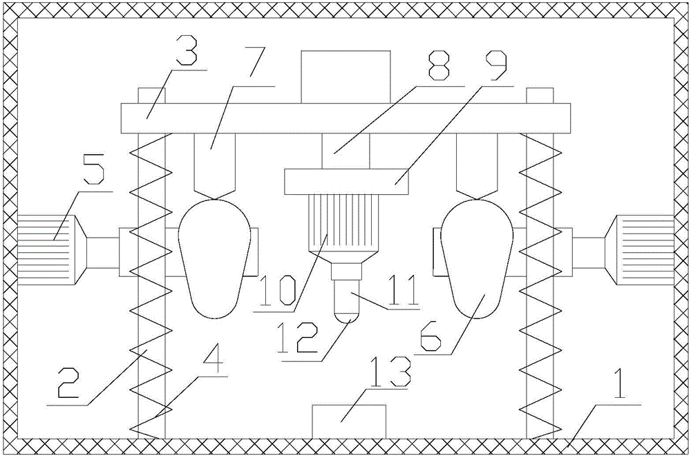
[0016] Such as figure 1 As shown, figure 1 It is a schematic structural diagram of a new type of self-chip removal machine tool proposed by the present invention.

[0017] Reference figure 1 , The new type of self chip removal machine tool proposed by the present invention includes: frame 1, guide rod 2, upper support plate 3, spring 4, first drive device 5, cam mechanism, second drive device 8, lower support plate 9, and Three driving device 10, drilling assembly and clamping part 13;

[0018] The guide rod 2 is arranged on the frame 1, the upper support plate 3 is slidably sleeved on the outer circumference of the guide rod 2, and the two ends of the spring 4 are respectively fixedly connected to the upper support plate 3 and the frame 1;

[0019] The first driving device 5 is arranged on the frame 1. The cam mechanism includes a cam 6 and a driven rod 7. The cam 6 is sleeved on the outer circumference of the output shaft of the first driving device 5, and is driven by the first...


PUM


Abstract

The invention provides a novel self-chip-removal machine tool. The cutting efficiency is effectively improved through vibrating drilling, and the novel self-chip-removal machine tool is smooth in chip removal and high in chip removal speed. A guide rod is arranged on the machine frame. An upper supporting plate is connected to the periphery of the guide rod in a vertical sliding and sleeving mode. The two ends of each spring are fixedly connected to the upper supporting plate and a machine frame respectively. A first drive device is arranged on the machine frame. A cam mechanism comprises a cam and a driven rod. The cam is connected to the periphery of an output shaft of the first drive device in a sleeving mode and is driven by the first drive device to rotate. One end of the driven rod is arranged on the upper supporting plate, and the other end of the driven rod abuts against the cam. A second drive device is arranged on the upper supporting plate and can drive a lower supporting plate to move in the axial direction of the guide rod. A third drive device is arranged on the lower supporting plate and can drive a drilling assembly to rotate. A drill stem is connected with an output shaft of the third drive device. A drill bit is arranged on the side, away from the third drive device, of the drill stem. The novel self-chip-removal machine tool is used for arranging a clamping piece on the machine frame, wherein the clamping piece is used for clamping workpieces.

Description

Technical field [0001] The invention relates to the technical field of machine tools, and in particular to a new type of self-chip removing machine tool. Background technique [0002] A machine tool is a machine that processes metal blanks into machine parts, and is called a machine tool or machine tool. In modern machinery manufacturing, there are many methods for processing parts, but all parts with high precision and surface roughness requirements are generally processed on the machine tool. Therefore, machine tools play an important role in the modernization of the national economy. A large amount of iron filings will be generated during the machining process of the machine tool, especially the deep hole machining process. If these iron filings are not discharged from the deep hole in time, the accumulated iron filings will seriously affect the machining accuracy of the drill and the processing quality of the workpiece. . The above-mentioned problems need to be solved urge...

Claims


Application Information

Patent Timeline
Patent Type & Authority Applications(China)
IPC IPC(8): B23B39/16B23B47/06B23B47/22B23B47/34
CPCB23B39/16B23B47/34B23Q5/167B23Q5/26B23Q5/32
Inventor 林锦富
Owner 蚌埠市金林数控机床制造有限公司
Learn More