Raman spectrum acquisition system with low background noise
A Raman spectrum and acquisition system technology, applied in Raman scattering, material excitation analysis, etc., can solve the problems of Raman spectrum information flooding and interference, and achieve the effects of reducing interference, increasing luminous flux, and improving signal-to-noise ratio
- Summary
- Abstract
- Description
- Claims
- Application Information
AI Technical Summary
Problems solved by technology
Method used
Image

Examples
Embodiment 1
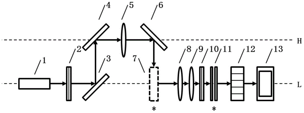
[0030] A Raman spectroscopy acquisition system with low background noise, see figure 1 , including: continuous laser 1, first filter 2, first converging lens 3, plane mirror 4, sample cell 5, second converging lens 6, third converging lens 7, second filter 8, slit 9. A spectroscopic device 10 and an array detector 11 .
[0031] The CW laser 1 generates a high-power, narrow-linewidth excitation beam, and the first filter 2 is a band-pass filter for filtering the stray light of the CW laser 1 itself. The first converging lens 3 converges the excitation beam, and bends the excitation beam through the plane mirror 4, so that the excitation beam is vertically incident on the sample from above (preferably directly above) the sample cell 5, and the excitation beam is excited at the sample cell 5. Mann scattered beams.
[0032] The linear excited region at the sample cell 5 is imaged at the slit 9 through the second converging lens 6 and the third converging lens 7, the height of th...
Embodiment 2
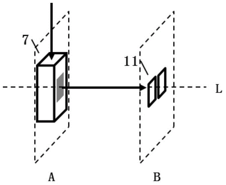
[0035] A Raman spectroscopy acquisition system with low background noise, see figure 1 with figure 2 , including: continuous laser 1, first filter 2, first converging lens 3, plane mirror 4, sample cell 5, second converging lens 6, third converging lens 7, second filter 8, slit 9. A spectroscopic device 10 and an array detector 11 .
[0036] The continuous laser 1 generates an excitation beam with a center wavelength of 532nm, a power not less than 50mW and a linewidth not greater than 0.6nm. The first optical filter 2 is a bandpass optical filter, which is used to filter out the stray light of the CW laser 1 itself. The first converging lens 3 converges the excitation beam, and bends the excitation beam through the plane mirror 4, so that the excitation beam is vertically incident on the sample from above (preferably directly above) the sample cell 5, and the excitation beam is excited at the sample cell 5. Mann scattered beams. The subsequent optical path mainly collect...
PUM
 Abstract
Description
Claims
Application Information
PatSnap Eureka turns technology decisions into work you can execute. Powered by our Innovation Knowledge Graph, it runs expert workflows across engineering, life sciences, materials and intellectual property. Get your review-ready output in minutes.


