
Micro-fluidic chip and applications thereof

A microfluidic chip and chip technology, applied in instruments, analyzing materials through chemical reactions, and analyzing materials through observation of the influence of chemical indicators, can solve problems such as identification, and achieve simple sample processing and low cost. Dosage, convenient modification effect

Active Publication Date: 2015-09-16
JIANGSU UNIV
View PDF7 Cites 5 Cited by
  • Summary
  • Abstract
  • Description
  • Claims
  • Application Information

AI Technical Summary

Problems solved by technology

These traditional detection methods each have their own scope and accuracy, and are also affected by cost, but these methods cannot be intuitively recognized by the naked eye

Method used


Image

  • Micro-fluidic chip and applications thereof
  • Micro-fluidic chip and applications thereof

Examples


Embodiment 1

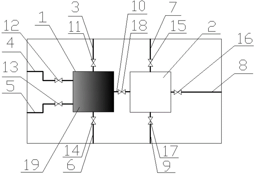
[0038] Step 1, open the first valve (11), close other valves, by the thia graphene / γ-Fe of 200 μ L 2mg / mL 2 o 3 The aqueous dispersion of the nanocomposite material is sent into the first mixing tank (1), the first valve (11) is closed, and the thia graphene / γ-Fe 2 o 3 After the nanocomposite is fixed on the bottom of the first mixing pool (1) by a powerful magnet (19), the fourth valve (14) is opened, the water is discharged through the pump, the fourth valve (14) is closed, and the first mixing pool (1) is dried. );

[0039] Step 2, open the second valve (12), close other valves, send 100 μ L of phosphate buffer solution (10 mM, pH=7.4) containing 0.5 units of lactate oxidase into the first mixing pool (1) through the pump, and close the second mixing pool (1). Valve (12); open the third valve (13), send 100 μL of phosphate buffer solution (10 mM, pH=7.4) containing 10 μmol of lactic acid into the first mixing tank (1) through the pump, and close the third valve (13) , i...

Embodiment 2

[0046] Step 1. Open the second valve (12), send 100 μL of phosphate buffer solution (10 mM, pH=7.4) containing 0.5 units of lactate oxidase into the first mixing pool (1) through the pump, and then close the second valve (12) ; Open the third valve (13), send 100 μL of phosphate buffer solution (10 mM, pH=7.4) containing 10 μmol of lactic acid into the first mixing pool (1) through the pump, close the third valve (13), and incubate the reaction ;

[0047] Step 2, open the eighth valve (18), send the mixed solution after the incubation reaction in step 1 to the second mixing tank (2) through the pump, and close the eighth valve (18);

[0048] Step 3, open the fifth valve (15), send 200 μ L of 0.2M acetic acid buffer solution (pH=4.0) into the second mixing tank (2) through the pump, close the fifth valve (15); open the sixth valve (16) , send 100 μL of an alcohol solution containing 0.5 mg 3,3',5,5'-tetramethylbenzidine into the second mixing pool (2) through a pump, close the...


PUM


Abstract

The invention provides a micro-fluidic chip and applications thereof. The micro-fluidic chip comprises a chip body made of a transparent material, the chip body comprises a first mixing tank and a second mixing tank which are connected with each other through a micro-channel, and an eighth valve is arranged on the micro-channel; the first mixing tank is connected with a first sample introduction micro-channel, a second sample introduction micro-channel, a third sample introduction micro-channel and a first sample discharge micro-channel, a first valve is arranged on the first sample introduction micro-channel, a second valve is arranged on the second sample introduction micro-channel, a third valve is arranged on the third sample introduction micro-channel, and a fourth valve is arranged on the first sample discharge micro-channel; the second mixing tank is connected with a fourth sample introduction micro-channel, a fifth sample introduction micro-channel and a second sample discharge micro-channel, a fifth valve is arranged on the fourth sample introduction micro-channel, a sixth valve is arranged on the fifth sample introduction micro-channel, and a seventh valve is arranged on the second sample discharge micro-channel. The micro-fluidic chip has good effect when used for detecting lactic acid by adopting a colorimetric method, and thus the prospect of the micro-fluidic chip in application field of the colorimetric method is disclosed.

Description

technical field [0001] The invention relates to a microfluidic chip, specifically a microfluidic chip that can be used for colorimetric detection of specified substances, especially for modifying thia graphene / γ-Fe 2 o 3 Lactate was detected colorimetrically after nanocomposites. Background technique [0002] In recent years, the miniaturization of analytical devices has become an important research direction, and the development of microfluidic chip technology has also received extensive attention. The microfluidic chip is a microfluidic system composed of microfunctional components such as liquid reservoirs, microreaction chambers, and micropipes built on the chip through microfabrication technology. Form a microfluidic channel to perform one or multiple reactions on the chip in a row to achieve the purpose of high-throughput, low-consumption, and rapid analysis of samples. Due to its high integration, the microfluidic analysis chip can complete various functions such a...

Claims


Application Information

Patent Timeline
Patent Type & Authority Applications(China)
IPC IPC(8): G01N21/78G01N35/00
Inventor 毛罕平严玉婷
Owner JIANGSU UNIV
Learn More