Current enhanced type lateral insulated gate bipolar transistor

A bipolar transistor and current enhancement technology, which is applied in circuits, electrical components, semiconductor devices, etc., can solve the problems of increasing device off time, decreasing latch-up suppression ability, and withstand voltage drop, so as to improve the on-current density , Improving the latch-up suppression ability and the effect of improving the conduction current capability

Active Publication Date: 2015-09-16
SOUTHEAST UNIV +1
View PDF5 Cites 8 Cited by
  • Summary
  • Abstract
  • Description
  • Claims
  • Application Information

AI Technical Summary

Problems solved by technology

However, while these devices increase the on-current density, they will bring some new problems. For multi-channel LIGBTs, the number of carriers stored in the drift region before turning off is large, and there is no special hole-carrying The sub-draining channel increases the turn-off time of the device, and other technologies to increase the on-current density will also cause problems such as a drop in the withstand voltage of the device or a drop in the ability to resist latch-up.
The drop of the withstand voltage reduces the maximum working voltage of the device, which limits the application of the device; the increase of the off-time increases the switching loss of the device; the latch-up effect will cause the gate signal to lose control of the device, and the device structure may experience Destructive failure, the decline of latch-up suppression ability, which reduces the reliability of the device

Method used


Image

  • Current enhanced type lateral insulated gate bipolar transistor
  • Current enhanced type lateral insulated gate bipolar transistor
  • Current enhanced type lateral insulated gate bipolar transistor

Examples


Embodiment Construction

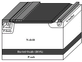
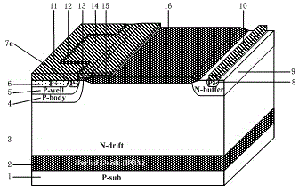
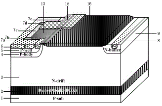
[0030] Combine below figure 2 , image 3 , to describe the present invention in detail, a current-enhanced lateral insulated gate bipolar transistor, comprising: a P-type substrate 1, a buried oxygen 2 is provided on the P-type substrate 1, and an N-type substrate is provided on the buried oxygen 2. In the drift region 3, a P-type body region 4 and an N-type buffer region 9 are respectively arranged on both sides of the N-type drift region 3, and a heavily doped P-type collector region 8 is arranged in the N-type buffer region 9. The mixed P-type collector region 8 is connected with an anode metal 10, and a field oxygen layer 16 is arranged above the N-type drift region 3. One side boundary of the field oxygen layer 16 falls above the N-type buffer zone 9, and the other One side boundary is in contact with the P-type body region 4 and is a straight boundary, a P-type well region 5 is arranged in the P-type body region 4, and a heavily doped P-type emitter region 6 is arrange...


PUM


Abstract

A current enhanced type lateral insulated gate bipolar transistor improves current density and the turn-off speed on the premise that a latching ability is maintained to be unchanged. The semiconductor is provided with buried oxide disposed on a P-type substrate and an N-drift region disposed on the buried oxide, a P-body region and an N-buffer region are disposed on the N-drift region, a P-type collecting electrode region is disposed in the N-buffer region, an anode metal is connected to the P-type collecting electrode region, a field oxide layer is disposed on the N-drift region, a P-well region is disposed in the P-body region, a P-type emitting electrode region and an emitting electrode region are disposed in the P-well region, the inner-side boundaries of the four regions, i.e., the P-body region, the P-well region, the P-type emitting electrode region and the emitting electrode region are synchronously recessed inwardly to form a square groove, the emitting electrode region surrounding the groove is successively defined as a first P-type emitting electrode region, second, third and fourth N-type emitting electrode regions and a fifth P-type emitting electrode region, the N-drift region protrudes outwardly and fills the square groove, a surface of the P-body region is provided with a gate oxide layer, a surface of the gate oxide layer is provided with a polysilicon layer, and a gate metal is connected to the polysilicon layer.

Description

technical field [0001] The invention mainly relates to the technical field of power semiconductor devices, and is a current-enhanced transverse insulated gate bipolar transistor, which is especially suitable for high-voltage three-phase single-chip inverter integrated circuits and used to drive DC brushless motors. Background technique [0002] Insulated Gate Bipolar Transistor IGBT is a composite power device evolved from the combination of MOS gate device structure and bipolar transistor structure. It has the characteristics of both MOS transistor and bipolar transistor, and has good on-state current and switching loss. compromise relationship between. Silicon-on-insulator lateral insulated gate bipolar transistor (SOI-Lateral Insulated Gate Bipolar Transistor, SOI-LIGBT) is a typical device based on SOI technology, which has the advantages of easy integration, high withstand voltage, strong drive current capability, and fast switching speed. And other advantages, it has ...

Claims


Application Information

Patent Timeline
Patent Type & Authority Applications(China)
IPC IPC(8): H01L29/739H01L29/06H01L29/08
CPCH01L29/0607H01L29/0808H01L29/7393
Inventor 孙伟锋祝靖张龙顾炎宋华张森苏巍
Owner SOUTHEAST UNIV
Why Eureka
Try Eureka