Complex force field spiral chute for ore dressing

A technology of spiral chute and compound force field, which is applied in the direction of solid separation, wet separation, chemical instruments and methods, etc., can solve the problems of lower recovery rate of useful minerals, high tailings grade, low enrichment ratio, etc., and achieve improved recovery The effect of increasing the rate, improving the concentrate grade, and increasing the enrichment ratio

Inactive Publication Date: 2015-09-23
UNIV OF SCI & TECH LIAONING
View PDF8 Cites 14 Cited by
  • Summary
  • Abstract
  • Description
  • Claims
  • Application Information

AI Technical Summary

Problems solved by technology

Aiming at the problems that fine-grained useful minerals are easily mixed into the tailing belt in today's spiral chute beneficiation, resulting in low concentrate grade, low enrichment ratio, high tailings grade, and reduced recovery rate of useful minerals in spiral chute beneficiation, a new type of mineral is needed. Composite force field spiral chute

Method used


Image

  • Complex force field spiral chute for ore dressing
  • Complex force field spiral chute for ore dressing

Examples


Embodiment Construction

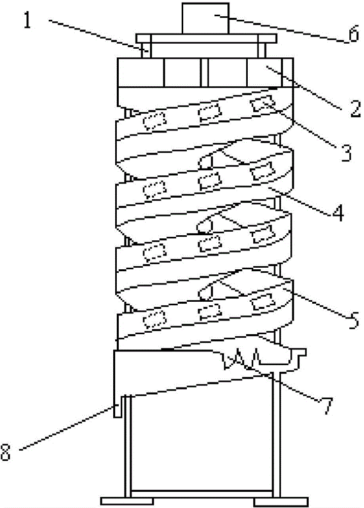
[0011] like figure 1 As shown, a compound force field spiral chute for mineral processing is composed of channel steel support 1, mine feeder 2, magnetic pole 3, pulsating pressure water tank 4, spiral blade 5, ore separating bucket 6, ore cutting bucket 7 and connection The ore bucket 8 is composed of the channel steel bracket 1 as a skeleton, the ore feeder 2, the magnetic pole 3, the pulsating pressure water tank 4, the spiral blade 5, the ore distribution bucket 6, the ore cutting bucket 7 and the ore bucket 8 are all attached to the channel steel On the bracket 1, the ore-distributing bucket 6 is installed on the uppermost end of the channel steel bracket 1, and the ore feeding device 2 is installed on the uppermost end of the spiral blade 5 under the ore-dividing bucket 6, and a magnetic pole 3 is installed on the inner and outer walls of the spiral blade 5. The magnetic pole 3 provides a magnetic field, and a pulsating water tank 4 is installed below the helical blade 5...


PUM


Abstract

The present invention discloses a complex force field spiral chute for ore dressing, and fine particles can be effectively prevented from entering into a tailing zone. The spiral chute comprises a channel steel support, an ore-feeding device, magnetic poles, a pulsating pressure water tank, a spiral blade, an ore dividing bucket, an ore intercepting bucket and an ore receiving bucket. The permanent magnetic fixed magnetic poles are installed at an external portion of a spiral blade of an existing spiral chute, so that magnetic fine particles in magnetic mineral can be forced by an inward-radial magnetic retentive force to enter into a concentrate zone under the function of an applied magnetic field. The pulsating water tank is installed at the bottom of a spiral surface, ore particles are prevented from rubbing with the spiral surface, so that the ore particles can be well layered and separated conveniently, and equipment abrasion can be eliminated conveniently. Concentrate grades can be improved, concentration ratio can be increased, mineral recovery rates can be improved, an existing spiral ore dressing technology can be simplified, and equipment maintenance rates and equipment power consumption can be reduced.

Description

technical field [0001] The invention relates to a mineral processing device, in particular to a compound force field spiral chute for mineral processing. Background technique [0002] Spiral beneficiation is one of the simple and efficient beneficiation methods and has been widely used in the industry. This method has the advantages of no power consumption and no environmental pollution. In 1941, B. Humphrey invented the spiral concentrator, mainly for pyrite separation of associated gold in Colorado. The spiral concentrator prototype is made of old truck tires in the shape of a spiral groove. Due to the depression of the gold mining industry in the United States, the first industrial spiral concentrator for sorting chromite ore was installed in Oregon in 1943, followed by Florida in 1944 for sorting titanium ore from seaside placer . The spiral concentrator is made of cast iron, made into a semicircle, and connected together with bolts. Each spiral weighs about 1 ton. S...

Claims


Application Information

Patent Timeline
Patent Type & Authority Applications(China)
IPC IPC(8): B03B5/62
Inventor 王恩雷崔録赵通林段风梅
Owner UNIV OF SCI & TECH LIAONING
Why Eureka
Try Eureka