
A hydraulic free piston engine

A piston engine and hydraulic technology, which is applied in the power and hydraulic fields, can solve problems such as excessive coaxiality requirements, constraints, and poor processing technology of piston components, so as to improve the compactness of the structure, simplify the structure, and reduce the technology. Effect

Active Publication Date: 2017-04-12
BEIJING INSTITUTE OF TECHNOLOGYGY
View PDF6 Cites 0 Cited by
  • Summary
  • Abstract
  • Description
  • Claims
  • Application Information

AI Technical Summary

Problems solved by technology

However, due to the need to increase the recovery system of the power piston, the axial dimension of the piston assembly in these two arrangements will be too large (at least more than twice the piston stroke) or the radial dimension of the pump body part will be too large, so that the hydraulic pressure is free. Piston engines are not compact in structure, the processing technology of piston components is deteriorated, and the coaxiality between the cylinder block and the corresponding cavity of the pump piston is too high, etc., which have seriously restricted and limited the further application and promotion of hydraulic free piston engines.

Method used


Image

  • A hydraulic free piston engine
  • A hydraulic free piston engine
  • A hydraulic free piston engine

Examples


Embodiment Construction

[0020] The specific embodiments of the present invention will be described in detail below with reference to the accompanying drawings. However, the embodiments of the present invention are not limited to this.

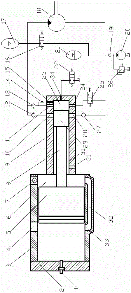
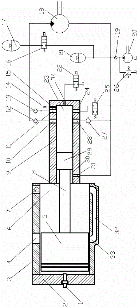
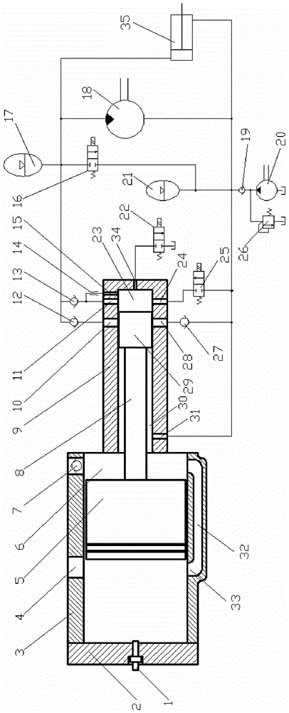
[0021] Generally, the low pressure end of the hydraulic system is atmospheric pressure, or in order to ensure that the pump piston does not appear cavitation when sucking oil, the low pressure end pressure is increased to 0.5 MPa, and the output high pressure oil pressure is more than ten MPa or tens of MPa. The basic idea of ​​the technical solution of the present invention is to increase the pressure at the low pressure end of the hydraulic free piston engine from the traditional atmospheric pressure or 0.5MPa pressure to a pressure sufficient to drive the piston assembly to complete the compression stroke, such as a higher pressure of 5MPa. This pressure is sufficient to push the piston assembly to complete the compression stroke of the power piston. When the piston ...


PUM


Abstract

The invention discloses a hydraulic free piston engine. A power piston and a pump piston are in rigid connection through a piston rod to form a piston assembly. The movable piston is disposed in a cylinder, and the pump piston is disposed in a pump. The pump piston is in a differential-pressure stage piston structure, and the pump is provided with hydraulic channels with different diameters. The hydraulic channels are connected with a hydraulic system, and the hydraulic system is a differential-pressure closed type hydraulic system. Through the above technical scheme of the invention, the engine can simplify the structure, reduces the manufacturability of actual manufacturing and machining, and further improving the structural compactness.

Description

Technical field [0001] The invention relates to the field of power and hydraulic technology, in particular to a hydraulic free piston engine. Background technique [0002] The hydraulic free piston engine is a power machine that integrates a reciprocating piston internal combustion engine and a plunger hydraulic pump. The hydraulic free piston engine directly converts the heat energy of fuel combustion into hydraulic energy for external output through a reciprocating piston assembly. It has the advantages of simple structure, short transmission chain, variable compression ratio, and flexible medium for power transmission. It can be used as a power source for vehicles and other mobile equipment, and is especially suitable for mobile devices that use hydraulic pressure as a power source. [0003] At present, from the perspective of the structural types that realize the principle of the hydraulic free piston engine, there are two forms: one is to connect three pistons such as the powe...

Claims


Application Information

Patent Timeline
Patent Type & Authority Patents(China)
IPC IPC(8): F02B71/04F02B71/02F15B1/02F15B11/08F15B13/04
Inventor 赵振峰张付军赵长禄黄英张栓录
Owner BEIJING INSTITUTE OF TECHNOLOGYGY
Learn More