contains co 2 and h 2 s gas recovery system and recovery method

A recovery system and recovery method technology, applied in the removal of gas pollutants, gas treatment, separation methods, etc., can solve the problems of heat energy increase, absorption speed decrease, etc., and achieve the effect of heat reduction and selective separation improvement

Active Publication Date: 2016-11-30
三菱重工工程株式会社
View PDF7 Cites 0 Cited by
  • Summary
  • Abstract
  • Description
  • Claims
  • Application Information

AI Technical Summary

Problems solved by technology

[0010] However, the technique of Patent Document 1 is applied to 2 S gas recovery CO 2 is valid, but when applied from CO containing 2 and H 2 S gas selective recovery of H 2 When S, there is the following problem, that is, due to the H in the absorption liquid below the absorption tower 2 The S concentration becomes higher, causing the H 2 The rate of S absorption is greatly reduced, so the H 2 S removal rate, H 2 S selectivity decreases, in order to obtain the desired removal rate, it leads to an increase in heat energy

Method used


Image

  • contains co  <sub>2</sub> and h  <sub>2</sub> s gas recovery system and recovery method
  • contains co  <sub>2</sub> and h  <sub>2</sub> s gas recovery system and recovery method
  • contains co  <sub>2</sub> and h  <sub>2</sub> s gas recovery system and recovery method

Examples


Embodiment 1

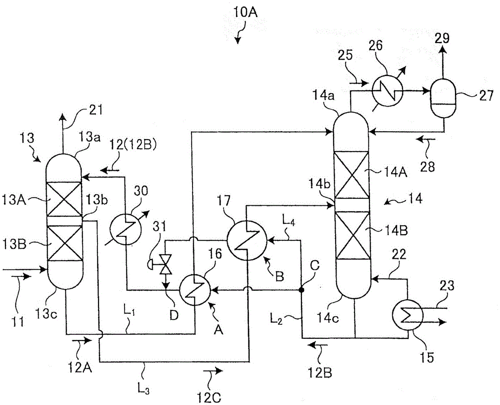
[0033] Containing CO to the embodiment of the present invention with reference to accompanying drawing 2 and H 2 The recovery system of S gas will be described. figure 1 It is the containing CO of embodiment 1 2 and H 2 Schematic diagram of the S gas recovery system. figure 2 Containing CO other than Example 1 2 and H 2 Schematic diagram of the S gas recovery system.

[0034] Such as figure 1 As shown, the CO contained in this example 2 and H 2 The recovery system 10A of S gas is equipped with: an absorption tower 13 : it uses, for example, CO-containing gas obtained from a gasification furnace for gasifying coal or biomass, etc. 2 and H 2 The vaporized gas of S is used as the introduction gas 11, so that the introduction gas 11 and the absorption of CO 2 and H 2 The absorption liquid 12 of S contacts and absorbs CO from the introduction gas 11 2 and H 2 S; absorption liquid regeneration tower (hereinafter referred to as "regeneration tower") 14: it will absorb ...

Embodiment 2

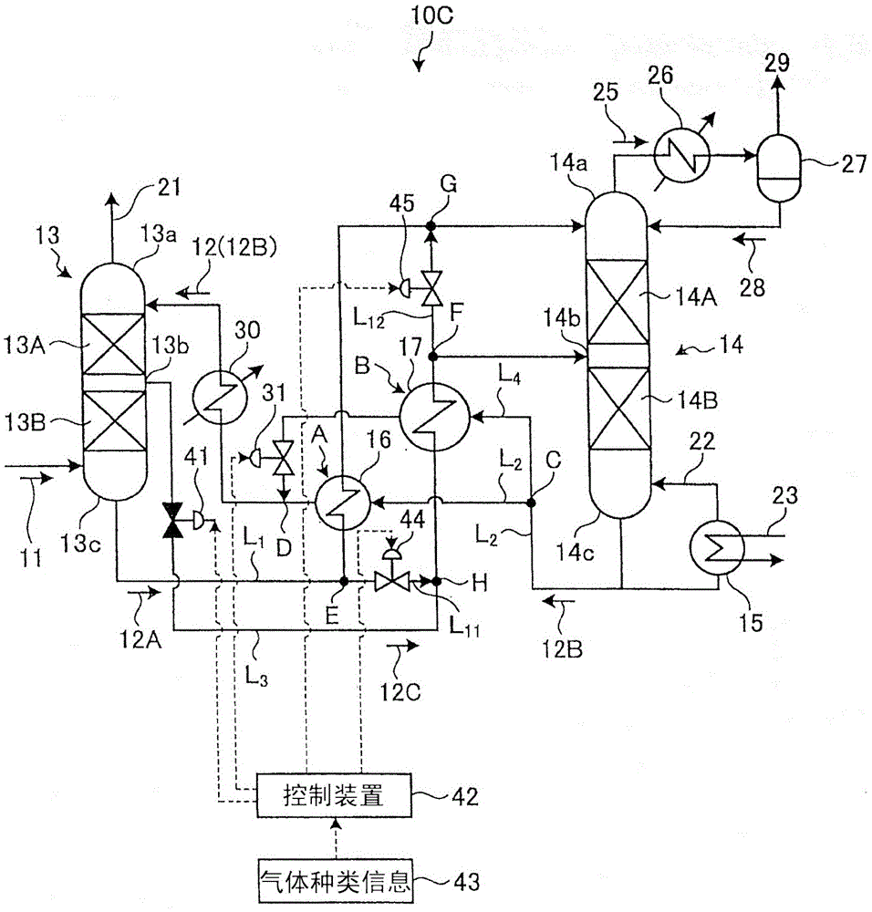
[0068] Referring to the accompanying drawings, the CO-containing 2 and H 2 S gas recovery system. image 3 It is the containing CO of embodiment 2 2 and H 2 Schematic diagram of the gas recovery system for S.

[0069] Such as image 3 As shown, the CO contained in this example 2 and H 2 S gas recovery system 10C is equipped with: 1st bypass line L 11 : It takes out the rich solution 12A and makes it installed in the rich solution supply line L 1 The branch part E on the upstream side of the first heat exchanger 16 is supplied from the rich solution supply line L 1 Side bypass to semi-rich solution supply line L 3 side, the rich solution 12A is introduced into the second heat exchanger 17; the second bypass line L 12 : which makes the supply line L from the semi-rich solution 3 Side detour at branch F to rich solution supply line L 1 The rich solution 12A that has undergone heat exchange is installed in the semi-rich solution supply line L 3 The confluence part G o...


PUM


Abstract

The system is provided with: a first heat exchanger which is interposed at an intersection between a rich solution supply line and a lean solution supply line, which has absorbed CO2 and H2S extracted from a bottom portion of an absorber, and a regenerated absorbent; a second heat exchanger which is interposed at an intersection between a semi-rich solution supply line and a branch line branched at the branch portion C from the lean solution supply line, and the lean solution; a merging portion which merges a branch line configured to supply the lean solution after heat exchange with the lean solution supply line; and a flow rate adjusting valve which is interposed in the lean solution supply line to adjust the distribution amount of the lean solution.

Description

technical field [0001] The present invention relates to CO contained in gasification gas obtained by gasifying, for example, coal, biomass, etc., using a gasifier. 2 and H 2 Efficient recovery of H from S 2 S containing CO 2 and H 2 S gas recovery system and method. Background technique [0002] As a method for removing CO contained in gasification gas obtained by gasifying coal, biomass, etc. in a gasifier 2 and H 2 For the technology of acid gases such as S, so far, chemical absorption methods (for example, amine absorption liquids (for example (using N-methyldiethanolamine: MDEA and other absorption liquids)) and physical absorption methods (for example, using poly Selexol absorption solution of ethylene glycol dimethyl ether). [0003] However, in the case of a system such as IGCC (Coal Gasification Combined Power Generation) technology, the following requirements are required. [0004] 1) In the power generation system, in order to make the air pollutant SO X T...

Claims


Application Information

Patent Timeline
Patent Type & Authority Patents(China)
IPC IPC(8): B01D53/14C01B17/16C10K1/08C01B32/40C01B32/50
CPCB01D53/1425B01D53/1462B01D2252/2026B01D2252/20484B01D2252/20489B01D2256/245C01B17/167C10K1/004C10K1/005C10K1/08Y02C20/40Y02P20/151B01D53/1468B01D53/1475B01D53/185B01D53/526B01D2252/204
Inventor 堀添浩司加藤雄大村上盛纪汤岛昌记石田一男
Owner 三菱重工工程株式会社
Why Eureka
Try Eureka