Direct coal liquefaction process

A direct coal liquefaction technology, applied in the preparation of liquid hydrocarbon mixtures, petroleum industry, etc., can solve the problems of low solid content and liquid content, increase in coal residence time liquefaction reactor volume, high gas content, etc. The effect of reducing complexity and capital costs

Inactive Publication Date: 2015-09-23
ACCELERGY CORP
View PDF13 Cites 3 Cited by
  • Summary
  • Abstract
  • Description
  • Claims
  • Application Information

AI Technical Summary

Problems solved by technology

This high gas holdup and correspondingly low solid and liquid holdups lead to an increase in the liquefaction reactor volume required to achieve a given coal residence time and conversion of coal to liquid products

Method used


Image

  • Direct coal liquefaction process
  • Direct coal liquefaction process
  • Direct coal liquefaction process

Examples


Embodiment

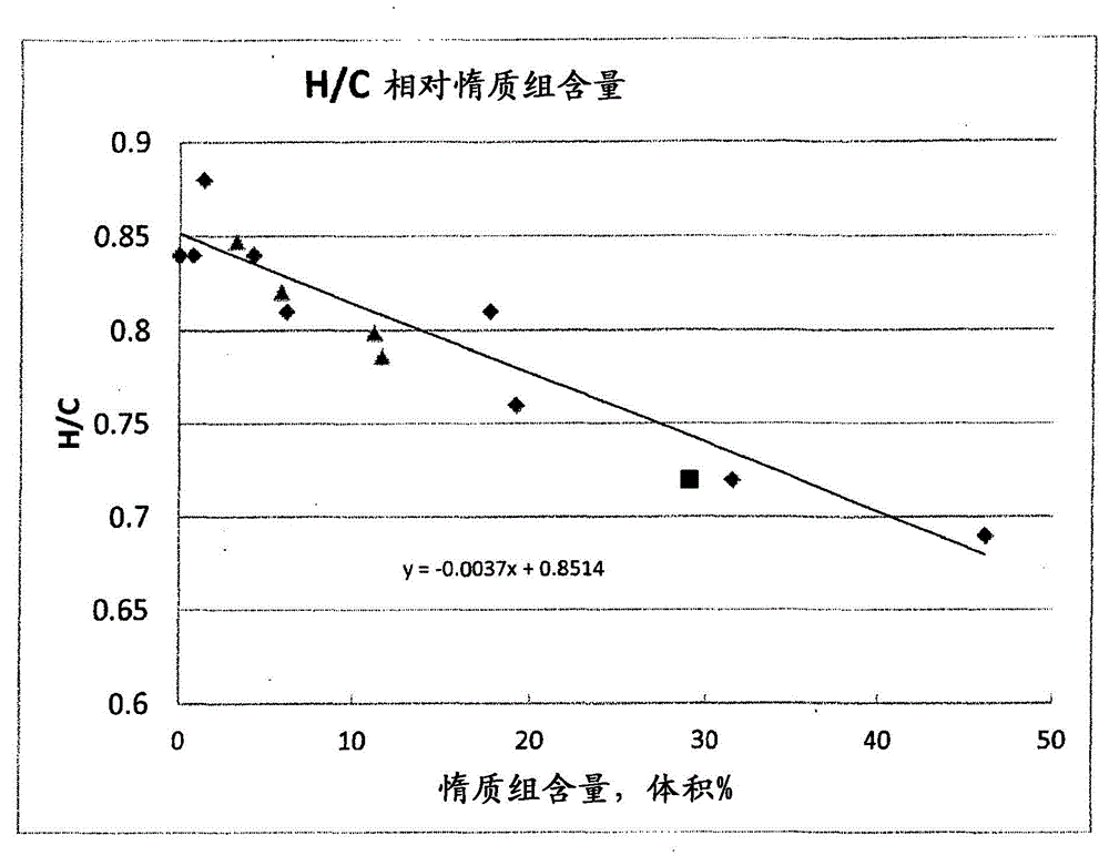
[0043]The process of the invention was carried out in the same 0.1 t / d pilot plant as used in the experiments described by Wasaka. The pilot plant was tuned for slurry mixing tank, pumps, slurry reactor, microcatalyst (molybdenum) addition and 600-700°F + recirculation. Compared with Wasaka's pilot plant operation, the slurry feed flow rate increased to 10-12kg / h, and the gas flow rate decreased by 2-4 times. During the run of the pilot plant, the reactor experienced no solids buildup or reactor deposits. The coal used in this example was in figure 1 The plot for is represented as a square symbol, and is thus consistent with the overall trend of H / C relative to inertinite content.

[0044] The oil yield at a non-donor 650°F+ (343°C) recycle stream to coal ratio of 1.5 / 1 was 44.6 wt% (on a MAF basis). When at 0.73Nm 3 Low H / kg slurry 2 The C5+ / 371°C (C5 / 650°F) yield increased to 66.4 wt% at the feed flow rate of 650°F+ when the stream ratio was increased to 3 / 1. This is ...


PUM

PropertyMeasurementUnit
thermal efficiencyaaaaaaaaaa

Abstract

A direct coal liquefaction method and apparatus in which the feed coal is mixed with a recycled 600° F+ non-donor stream in which the ratio of coal to said stream is at least 1.5:1 on a moisture free basis to form an input slurry to a DCL reactor. Hydrogen containing treat gas is supplied to the reactor. 1000° F- bottoms from the reactor are recycled as part of the 600° F+ non-donor stream. 1000° F + bottoms from the reactor are gasified in a POX unit to provide hydrogen for the DCL reaction. The ratio of recycled bottoms to feed coal is between 1:0.5 and 1:1.5.

Description

technical field [0001] The invention relates to a direct coal liquefaction method, which can produce gasoline, jet fuel or diesel oil from coal with high inertinite content with high thermal efficiency. Background technique [0002] Increases in the cost of petroleum and concerns about future shortages have led to increased interest in using the large, readily available deposits of coal, which exist in various parts of the world, as a fuel source. Different methods have been proposed to convert coal into liquid and gaseous fuel products including gasoline, diesel fuel, aviation turbine fuel and heating oil, and in some cases into other products such as lubricants and chemicals. However, many issues have hindered the promotion of coal liquefaction, including the relatively low thermal efficiency of indirect coal-to-liquids (CTL) conversion methods such as Fischer-Tropsch (FT) synthesis and methanol-to-liquids (MTL) conversion and the 2 emissions concerns. [0003] A coal li...

Claims


Application Information

Patent Timeline
Patent Type & Authority Applications(China)
IPC IPC(8): C10G1/06
CPCC10G1/086C10G1/065
Inventor R·F·保曼P·S·马
Owner ACCELERGY CORP
Why Eureka
Try Eureka