
Piezoelectric vibrating body

A technology of piezoelectric vibration and piezoelectric layer, which is applied in piezoelectric-electric polymer transducers, circuits, piezoelectric/electrostrictive transducers, etc. Hard vibrating plate resonance and other problems

Active Publication Date: 2015-09-30
MURATA MFG CO LTD +1
View PDF8 Cites 7 Cited by
  • Summary
  • Abstract
  • Description
  • Claims
  • Application Information

AI Technical Summary

Problems solved by technology

Then, compared with PZT and other piezoelectric ceramics, the piezoelectric body made of polymer has low piezoelectricity and weak force, so it is not suitable for resonating a hard vibration plate, and as in the above-mentioned Patent Documents 1 and 2 , using the method of using the bending vibration of the piezoelectric body

Method used

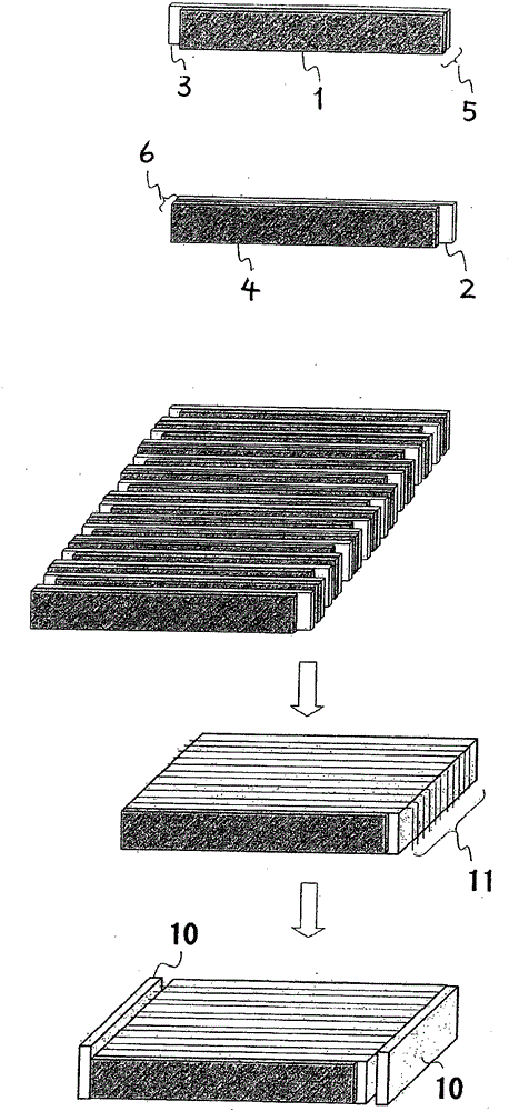
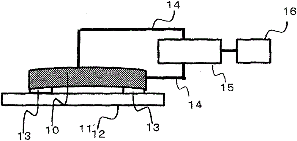
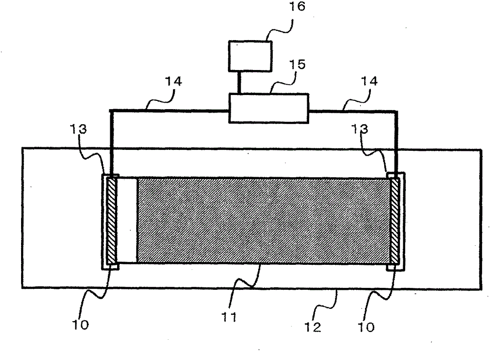

Image

  • Piezoelectric vibrating body
  • Piezoelectric vibrating body
  • Piezoelectric vibrating body

Examples


Embodiment

[0163] Hereinafter, the present invention will be further specifically described through examples, but the present invention is not limited thereto. The physical properties of each layer and the piezoelectric speaker were evaluated by the following methods.

[0164] (1) Physical properties of each layer

[0165] The end portions of the laminate were notched very equally, and the layers were peeled off to evaluate the physical properties of the layers.

[0166] (1-1) Main orientation direction

[0167] Using an ellipsometer (type M-220; JASCO), the obtained film was subjected to a transmitted light measurement in which the incident angle of 550 nm monochromatic light was changed, and the sample stage fixed with the film was set at a distance relative to the optical axis. The in-plane rotation with the optical axis perpendicular is performed, and the direction in which the refractive index in the in-plane direction is the highest is obtained, and this direction is defined as t...

Synthetic example 1

[0176] Synthesis Example 1: Synthesis of poly-L-lactic acid (PLLA)

[0177] Nitrogen replacement was carried out in the vertical stirring tank (40L) equipped with all-area wings equipped with vacuum piping, nitrogen piping, catalyst addition piping, L-lactide solution addition piping, and ethanol initiator addition piping. After that, load 30Kg of L-lactide, 0.90kg of stearyl alcohol (0.030 mol / kg), 6.14g of stannous octoate (5.05×10⁻⁴ mol / 1kg), and raise the temperature to 150°C under a nitrogen pressure of 106.4kPa . Stirring was started when the contents were dissolved, and the internal temperature was further raised to 190°C. Since the reaction started when the internal temperature exceeded 180° C., the reaction was continued for 1 hour while maintaining the internal temperature at 185° C. to 190° C. while cooling. Furthermore, after stirring and reacting for 1 hour at 106.4 kPa of nitrogen pressure and 200 degreeC - 210 degreeC of internal temperature, stirring was stop...

Synthetic example 2

[0180] Synthesis example 2: Synthesis of poly D-lactic acid (PDLA)

[0181] In addition, except that D-lactide was used instead of L-lactide, in the same manner as in Synthesis Example 1, a glass transition temperature (Tg) of 55°C, a melting point (Tm) of 175°C, a weight average molecular weight of 120,000, and a molecular weight of D-lactic acid (PDLA) with a variance of 1.8 and a lactide content of 0.005% by mass.


PUM


Abstract

The purpose of the present invention is to provide a piezoelectric vibrating body that is capable of instantaneously generating vibrations for causing what is referred to as a haptic sensation by effectively generating sound waves when a voltage is applied thereto. This piezoelectric vibrating body comprises a piezoelectric laminated body, for which oriented film layers made of a polylactic acid and conductive layers are alternatingly laminated, and grippers for gripping either end of the piezoelectric laminated body, wherein (i) one of conductive layers adjoined across a respective oriented film layer is short-circuited to a negative electrode, and the other to a positive electrode, and the oriented film layers sandwiched by the respective conductive layers are laminated so as to expand / contract in the same direction when a current is applied thereto, (ii) the piezoelectric laminated body has two parallel surfaces that are parallel to the plane direction of the oriented film layers and two end faces A and B that are sandwiched by the parallel surfaces and arranged parallel to each other, and (iii) the gripped ends respectively include end face A and end face B, and the portion of the piezoelectric laminated body between the end faces A and B is stressed by the grippers.

Description

technical field [0001] The present invention relates to a piezoelectric vibrator using an alignment layer made of polylactic acid. Background technique [0002] Patent Document 1 discloses a technique for improving listening performance from the speaker by installing a transparent piezoelectric film speaker on the display surface of a mobile phone in a curved manner to output sound from a wide range. Furthermore, it is specifically disclosed that a method is proposed in which a rectangular PVDF (polyvinylidene fluoride) film is laminated using a so-called bimorph element (bimorph) structure that exhibits expansion and contraction behavior in opposite directions when electric charges are applied. One surface layer side and the other surface layer side in the thickness direction of the film are fixed and the two short sides are fixed, and a sound is emitted by vibrating the membrane to bend. [0003] In addition, Patent Document 2 proposes a piezoelectric speaker in which an ...

Claims


Application Information

Patent Timeline
Patent Type & Authority Applications(China)
IPC IPC(8): H04R17/00H01L41/083H01L41/193H01L41/277
CPCH04R7/04H01L41/277H01L41/083H04R17/005H01L41/193H10N30/50H10N30/057H10N30/857H10N30/20H10N30/871H10N30/886
Inventor 吉田哲男田实佳郎加藤温子
Owner MURATA MFG CO LTD
Learn More