

Welding method and application of maritime work high-strength steel plates
A technology of high-strength steel plates and welding methods, applied in welding equipment, welding/welding/cutting items, manufacturing tools, etc., can solve problems such as uneconomical, low impact absorption energy of welds, and difficulty in meeting the requirements of classification societies , to achieve the effect of reducing thermal energy consumption, high economy, and reducing welding workload
- Summary
- Abstract
- Description
- Claims
- Application Information
AI Technical Summary
Problems solved by technology
Method used
Image

Examples
Embodiment 1
[0029] 50mm thickness Q500E horizontal butt welding, specific process and implementation steps:
[0030] ① Welding materials
[0031] Flux cored wire YCJ551K2, specification Φ1.2; CO 2 Gas, purity 99.95%; welding parameters: current 220~230A, voltage 26~27V, welding speed 36~42cm / min.
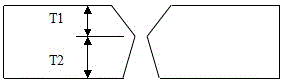
[0032] ② Groove form
[0033] Take an asymmetrical X-groove (such as figure 1 As shown), the groove angle is 45° on the T1 side and 40° on the T2 side, leaving a gap of 2mm at the root of the groove, and the thickness of both sides is 22mm on the T1 side and 28mm on the T2 side.
[0034] ③The implementation steps are:
[0035] First, arrange far-infrared heating devices on both sides of the steel plate, preheat to 100 ° C ~ 150 ° C within 500 mm from the groove, and use thermal insulation blankets to prevent heat dissipation.
[0036] Secondly, on the deep side of the groove (T2 side), use YCJ551K2 flux-cored wire for back welding of 3~4 layers, the welding thickness is about 14mm, and the...
Embodiment 2
[0060] 60mm thickness Q500E horizontal T-joint welding, specific process and implementation steps:
[0061] ① Welding material
[0062] Flux cored wire YCJ551K2, specification Φ1.2; CO 2Gas, purity 99.95%; welding parameters: current 220~230A, voltage 26~27V, welding speed 36~42cm / min.
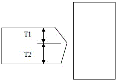
[0063] ② Groove form
[0064] Take an asymmetrical K-groove (such as figure 2 As shown), the groove angle is 40° on the T1 side and 40° on the T2 side, leaving a gap of 2mm at the root of the groove, and the thickness of both sides is 27mm on the T1 side and 33mm on the T2 side.
[0065] ③The implementation steps are:
[0066] First, arrange far-infrared heating devices on both sides of the steel plate, preheat to 100 ° C ~ 150 ° C within 500 mm from the groove, and use thermal insulation blankets to prevent heat dissipation.
[0067] Secondly, on the deep side of the groove (T2 side), use YCJ551K2 flux-cored wire for back welding of 3~4 layers, the welding thickness is about 14mm, and t...
PUM
| Property | Measurement | Unit |
|---|---|---|
| Tensile strength | aaaaa | aaaaa |
| Tensile strength | aaaaa | aaaaa |
| Hardness | aaaaa | aaaaa |
Abstract
Description
Claims
Application Information