Nozzle, nozzle mould and machining methods of nozzle and nozzle mould

A processing method and nozzle technology, applied in the field of 3D printing, can solve problems such as unsatisfactory requirements, and achieve the effects of high aspect ratio, high forming precision, and good processing precision

Active Publication Date: 2015-10-14
NINGBO INST OF MATERIALS TECH & ENG CHINESE ACADEMY OF SCI
View PDF7 Cites 13 Cited by
  • Summary
  • Abstract
  • Description
  • Claims
  • Application Information

AI Technical Summary

Problems solved by technology

[0007] In the process of manufacturing nozzles by powder micro-injection molding method, because the size of the inner hole of the nozzle is very small (μm level), the size of the corresponding template of the inner hole of the nozzle is also very small. Small-aperture nozzles) put forward higher process requirements. At this time, the use of nanoimprinting or machining to prepare inner hole templates can no longer meet the requirements.

Method used


Image

  • Nozzle, nozzle mould and machining methods of nozzle and nozzle mould
  • Nozzle, nozzle mould and machining methods of nozzle and nozzle mould
  • Nozzle, nozzle mould and machining methods of nozzle and nozzle mould

Examples


Embodiment 1

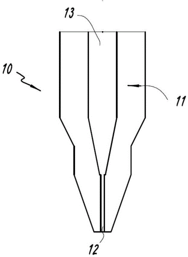
[0054] Such as figure 1 As shown, the nozzle 10 includes: a nozzle body 11 , a nozzle cavity 13 and a nozzle hole 12 . Wherein, nozzle cavity 13 can be polyhedron, cylinder or conical structure, and its top is connected with nozzle channel 12, and nozzle channel 12 is cylindrical, and can also be right cylinder, or elliptic cylinder, or paraboloid, or truncated. The head cone or multi-section structure, the centerline diameter of the nozzle hole 12 is a straight line, and can also be designed as a straight line, a curve, or even a spiral structure according to needs. The nozzle inner cavity 13 communicates with the first material sampling device. In this embodiment, the nozzle 10 is an array structure.

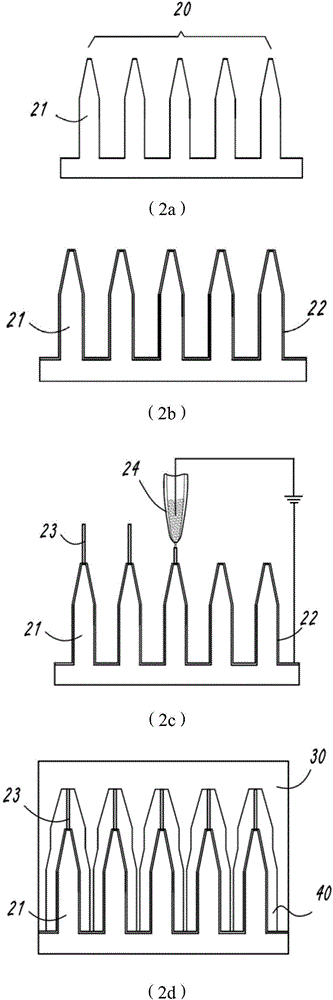
[0055] Such as figure 2 As shown, the nozzle 10 process of processing the present embodiment is as follows:

[0056] (1) figure 2 In 2a, high-strength gypsum powder, water and 801 glue are used to form a slurry with a mass fraction ratio of 50:20:3, and sulfur tires are ...

Embodiment 2

[0061] The nozzle structure of this embodiment is similar to that of Embodiment 1. Except for the structure of the inner mold 21 and the shape and size of the core, all the other structures are the same as that of Embodiment 1. The top end of the inner mold 21 of Embodiment 1 is a conical truncated cone, such as Figure 4 Shown, and the top end of the inner mold 21 of the present embodiment is conical shape, as Figure 5 shown.

[0062] Present embodiment processes this nozzle 10 processes as follows:

[0063] (1) Adopt the method of mechanical processing, select copper metal material for use, remove the excess material of corresponding position through drilling, punching, grinding and other processing processes, obtain the outer mold 30 and inner mold 21 with smooth surface, inner mold 21 has a round table the top of the shape;

[0064] (2) Fix the inner mold 21 flatly on the three-dimensional mobile platform of the three-dimensional micro-nano structure manufacturing syste...

Embodiment 3

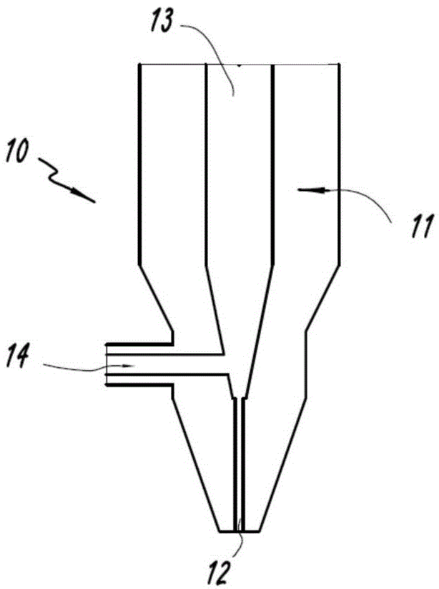
[0069] Such as image 3 As shown, the nozzle 10 of this embodiment includes: a nozzle body 11 , a nozzle inner cavity 13 , a nozzle hole 12 and an injection side pipe 14 . The injection side pipe 14 is positioned at the side of the nozzle inner chamber 13 and communicates with the nozzle inner chamber 13. The second material, which is different from the first material of the printing material, is especially injected with gas, thereby suppressing the problem of lowering printing accuracy caused by the inertia of low-viscosity printing materials. For high-viscosity printing materials, or low-viscosity melt materials printed at relatively low temperatures, the injection side pipe 14 is not necessary, and can be added or deleted as required during the manufacturing process or closed during use.

[0070] Present embodiment processes this nozzle 10 processes as follows:

[0071] (1) adopt the method for stereolithography to process the outer mold 30 of conical nozzle and the inner...


PUM

PropertyMeasurementUnit
sizeaaaaaaaaaa
particle diameteraaaaaaaaaa

Abstract

The invention discloses a machining method of a nozzle mould. The machining method comprises the following steps that (1), an outer mould for limiting the outer contour of a nozzle and an inner mould for limiting an inner cavity of the nozzle are manufactured; (2), the discharging end of the inner mould is made to have electrical conductivity; and (3), the discharging end of the inner mould serves as a substrate, and a mould core for limiting a nozzle duct is formed at the discharging end of the inner mould in a sedimentation mode through an electrochemical direct sedimentation technology. The invention further discloses the nozzle, the nozzle mould and a machining method of the nozzle. The machined nozzle has the advantages of being smaller in aperture but higher in depth-to-width ratio. Meanwhile, the shape of the nozzle duct is adjusted and changed as needed and is not limited by a traditional machining means; more possibilities are provided for possible fluid flowing excepted angle/volume distribution in the practical use; the micron-sized small aperture and shape on-demand preparation of the nozzle duct can be achieved.

Description

technical field [0001] The invention relates to 3D printing technology, in particular to a nozzle, a nozzle mold and a processing method for the nozzle and the nozzle mold. Background technique [0002] 3D printing technology (also known as "additive manufacturing technology") can manufacture three-dimensional models or parts through layer-by-layer superposition methods based on three-dimensional graphic data provided by computer-aided design systems (CAD) without machining or grinding tools. Especially for objects with complex structures, it can greatly shorten the product development cycle, improve productivity and reduce production costs. [0003] Methods for manufacturing three-dimensional models or parts by depositing flowable molding materials in layers include melt extrusion molding (FDM) and material injection molding technology (MJ). This type of process is to extrude flowable liquid materials (such as colloid or liquid resin, etc.) or molten materials (such as PLA...

Claims


Application Information

Patent Timeline
Patent Type & Authority Applications(China)
IPC IPC(8): C25D1/10B28B1/00B28B7/00
Inventor 郭建军张帅许高杰
Owner NINGBO INST OF MATERIALS TECH & ENG CHINESE ACADEMY OF SCI
Why Eureka
Try Eureka