Hydrogen supply system for liquid hydrogen storage material for hydrogen internal combustion engine

A hydrogen internal combustion engine and liquid hydrogen storage technology, applied in the direction of charging systems, internal combustion piston engines, combustion engines, etc., can solve the problems of poisoning fuel cells, inconvenient use, high dehydrogenation temperature, etc., to improve energy utilization and save costs Effect

Active Publication Date: 2015-10-14
WUHAN HYNERTECH CO LTD
View PDF6 Cites 15 Cited by
  • Summary
  • Abstract
  • Description
  • Claims
  • Application Information

AI Technical Summary

Problems solved by technology

Taking Germany as an example, the liquid organic hydrogen storage technology developed can realize the hydrogen absorption/desorption cycle under milder conditions, but the released hydrogen contains by-product gases that are poisonous to fuel cells, and has important defects such as low capacity and inconvenient use. ; Japan is curr

Method used


Image

  • Hydrogen supply system for liquid hydrogen storage material for hydrogen internal combustion engine
  • Hydrogen supply system for liquid hydrogen storage material for hydrogen internal combustion engine

Examples


Embodiment 1

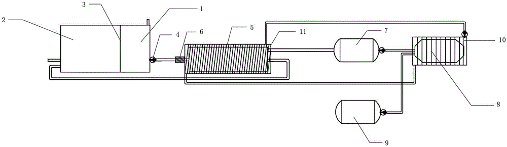
[0041] From figure 1It can be seen that the hydrogen storage tank used to store the liquid hydrogen source material and the liquid hydrogen storage carrier is provided with spaces for storing the liquid hydrogen source material and the liquid hydrogen storage carrier respectively: the first storage room 1 and the second storage room 2, two The storage compartments are separated by movable partitions 3. The first and second storage chambers are respectively provided with an input port and an output port, and the output port of the first storage chamber is provided with a pump 4 , through the operation of the pump, the liquid hydrogen source material is input into the reactor 5 through the input pipe. The reaction kettle adopts a plate reaction kettle, which is filled with a dehydrogenation catalyst.

[0042] A preheating device 6 is installed outside the input pipe connecting the pump and the reactor. The preheating device adopts an electric heater to preheat the liquid hydrog...

Embodiment 2

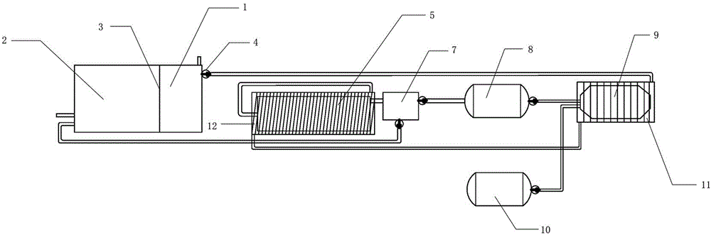
[0046] From figure 2 It can be seen that the hydrogen storage tank used to store the liquid hydrogen source material and the liquid hydrogen storage carrier is provided with spaces for storing the liquid hydrogen source material and the liquid hydrogen storage carrier respectively: the first storage room 1 and the second storage room 2, two The storage compartments are separated by movable partitions 3. The first and second storage chambers are each provided with an input port and an output port, and the output port of the first storage chamber is provided with a pump 4. Through the operation of the pump, the liquid hydrogen source material is input to the radiator 11 arranged outside the hydrogen internal combustion engine. In the pipeline, the heater 12 arranged outside the reactor and the radiator are connected through pipelines. The liquid hydrogen source material cools the hydrogen internal combustion engine and heats the reactor through heat exchange, and finally enters...


PUM

PropertyMeasurementUnit
Melting pointaaaaaaaaaa

Abstract

The invention discloses a hydrogen supply system for a liquid hydrogen source material for a hydrogen internal combustion engine. The hydrogen supply system comprises a hydrogen storage tank used for storing the liquid hydrogen source material and a liquid hydrogen storage carrier, a reaction kettle used for dehydrogenating the liquid hydrogen source material, a buffering tank used for storing hydrogen, an oxygen storage tank used for storing oxygen, a heat exchange device used for transmitting heat generated by the hydrogen internal combustion engine to the reaction kettle, and a hydrogen storage device which is used for conveying the liquid hydrogen source material into the reaction kettle through a pump. The dehydrogenation reaction of the liquid hydrogen source material is conducted in the reaction kettle; hydrogen generated through the reaction is conveyed to the buffering tank; meanwhile, the liquid oxygen storage carrier generated after dehydrogenation is conveyed back to the hydrogen storage tank; the hydrogen in the buffering tank and the oxygen in the oxygen storage tank enter the hydrogen internal combustion engine according to a proportion. According to the dehydrogenation device for the normal-temperature and normal-pressure liquid hydrogen source material for a hydrogen internal combustion engine automobile, a hydrogen storage and hydrogen internal combustion engine integrated technology for enabling the hydrogen released by liquid hydrogen source material dehydrogenation at the normal temperature and the normal pressure to directly enter a hydrogen internal combustion engine system is put forwards for the first time, according to the technology, a common car can run for 500 kilometers with the hydrogen generated by 80 L of an organic carrier, and therefore the cost for large-scale utilization of hydrogen energy in the future is greatly reduced.

Description

technical field [0001] The invention relates to the technical field of organic liquid hydrogen storage, in particular to a hydrogen supply system for liquid hydrogen storage materials used in hydrogen internal combustion engines. Background technique [0002] Hydrogen energy utilization technologies, such as hydrogen fuel cells and hydrogen internal combustion engines, can provide stable, efficient, and pollution-free power, and have broad application prospects in the fields of electric vehicles and mobile devices. In the past 10 years, developed countries such as the United States, Europe, and Japan, as well as Chinese government departments and enterprises have invested huge sums of money to develop the "hydrogen economy", and have made breakthroughs in large-scale hydrogen production and hydrogen fuel cells. In 2015, the world's major automakers (including SAIC) will mass-produce hydrogen fuel cell vehicles. According to the predictions of the U.S. Department of Energy a...

Claims


Application Information

Patent Timeline
IPC IPC(8): F02M21/02
CPCY02T10/30
Inventor 程寒松程健林安管一龙
Owner WUHAN HYNERTECH CO LTD
Why Eureka
Try Eureka