
One-step copper smelting process and device

A copper smelting device and copper smelting technology, applied in crucible furnaces, electric furnaces, rotary drum furnaces, etc., can solve the problems of easily damaged and eroded retaining wall refractory materials, poor quality of crude copper, and affecting production efficiency, so as to save fire Refining process, simple structure, strong adaptability

Active Publication Date: 2015-10-21
CENT SOUTH UNIV
View PDF7 Cites 19 Cited by
  • Summary
  • Abstract
  • Description
  • Claims
  • Application Information

AI Technical Summary

Problems solved by technology

The Mitsubishi method needs to be equipped with four furnaces, the installation needs a height difference, the construction cost is high, and the waste slag after the electric furnace is diluted has a high copper content; the flash continuous copper smelting method requires water quenching, drying, and fine grinding of the liquid copper matte , high energy consumption, and the copper content of the slag produced is as high as 10% to 20%, and the quality of blister copper is not good; the oxygen bottom blowing continuous copper smelting method uses two bottom blowing furnaces or three bottom blowing furnaces, showing a "one" word ladder Arrangement or arrangement in the form of "product" is a technology independently developed by my country; the Noranda continuous copper smelting method is directly producing blister copper in the early stage, because the slag contains high copper and has many impurities in blister copper, and the treatment of slag is complicated, so it is finally abandoned. Production of blister copper, still producing high-grade matte (70% Cu)
Since the high-temperature melt is easy to damage and corrode the refractory material of the retaining wall during operation, which affects the production efficiency, so this technology needs to be further improved.

Method used


Image

  • One-step copper smelting process and device
  • One-step copper smelting process and device

Examples


Embodiment 1

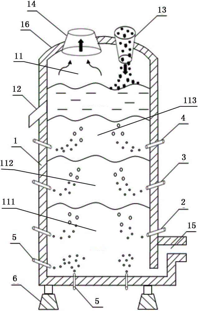
[0031] Such as figure 1 As shown, the one-step copper smelting device of the present invention includes a body of furnace 1 with a closed furnace chamber 11. The bottom of the body of furnace 1 is provided with a base 6, and the closed furnace chamber 11 is sequentially provided with a refining zone 111, a blowing chamber 11 from bottom to top. Smelting area 112 and smelting area 113, the furnace wall around refining area 111 is provided with a plurality of first spray guns 2, is provided with a plurality of second spray guns 3 on the furnace wall around blowing area 112, and the furnace wall around smelting area 113 A plurality of third spray guns 4 are arranged on the top, and a plurality of fourth spray guns 5 located below the third spray guns 4 are arranged on the furnace wall and bottom around the refining area 111, and a slagging outlet 12 is provided on the furnace wall above the smelting area 113. , The top wall 16 of the furnace body 1 is provided with a feeding port...

Embodiment 2

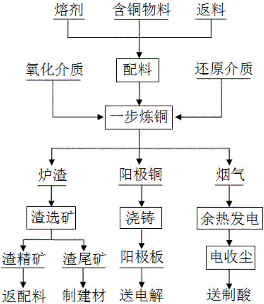
[0035] A kind of one-step copper smelting process that adopts said device, as figure 2 shown, including the following steps:

[0036] (1) After mixing the copper-containing material and flux, feed it into the furnace body 1 through the feeding port 13;

[0037] (2) Spray oxygen-enriched air into the smelting zone 113 through the third spray gun 4 for smelting, and smelt in the smelting zone 113 to form copper matte and slag, the grade of copper matte is 60%~75%, and the slag type Fe / SiO 2 In 1.4~2.2, the smelting temperature is controlled at 1180°C~1250°C, and the copper matte in the lower part of the smelting zone 113 is continuously oxidized into white matte. Because of its high density, it gradually moves down into the blowing zone 112. The generated copper matte is continuously replenished to the lower part of the smelting zone 113;

[0038] The oxygen-enriched air is sprayed into the blowing zone 112 through the second spray gun 3 for blowing. The blowing temperature is ...

Embodiment 3

[0046] A one-step copper smelting process, the one-step copper smelting process of this embodiment is basically the same as that of Embodiment 2, the difference is: the fourth spray gun 5 is not installed on the furnace wall around the refining area 111, but is installed at the bottom of the refining area 111 The fourth spray gun 5, during the refining and reduction process, only natural gas or pulverized coal is sprayed through the fourth spray gun 5 at the bottom of the refining zone 111 to deeply remove the O element in the copper liquid.


PUM


Abstract

The invention discloses a one-step copper smelting process and device. The device comprises a furnace body provided with a closed furnace chamber. From the bottom, the closed furnace chamber is sequentially provided with a refining area, a converting area and a smelting area from bottom to top. A plurality of first spray guns are arranged on the portions, around the refining area, of the furnace wall. A plurality of second spray guns are arranged on the portions, around the converting area, of the furnace wall. A plurality of third spray guns are arranged on the portions, around the smelting area, of the furnace wall. A plurality of fourth spray guns located below the first spray guns are arranged on the portions, around the refining area, of the furnace wall and / or the bottom. A slag discharging opening is formed in the portion, above the smelting area, of the furnace wall. A feeding port and a flue outlet are formed in the top of the closed furnace chamber. A copper discharging opening is formed in the bottom of the closed furnace chamber. The device has the advantages of being simpler in structure, durable, high in efficiency, less in investment, low in operation cost and the like; the process comprises the steps of distributing and discharging materials, carrying out smelting, converting and refining respectively, carrying out anode copper electrolysis, and treating slag and smelter off-gas, and has the advantages of being short in flow, high in adaptability, low in energy consumption, environmentally friendly and the like.

Description

technical field [0001] The invention relates to the technical field of nonferrous metal metallurgy, in particular to a one-step copper smelting process and device. Background technique [0002] The existing copper pyrometallurgical process is mainly divided into three processes: smelting, blowing and refining. [0003] In terms of smelting, the methods mainly include flash smelting and molten pool smelting, specifically Outokumpu flash smelting, Inco flash smelting, Noranda smelting, Osmelt smelting, Isa smelting, oxygen smelting Bottom blowing smelting, silver smelting, Vanyukov smelting, Tenient smelting, Mitsubishi smelting, Kaldor furnace smelting, rotary float smelting and traditional reverberatory furnace smelting, blast furnace smelting, electric furnace smelting, etc. At present, the traditional smelting process is being replaced by clean and intensified smelting technology, but modern intensified smelting technology also has some problems, such as flash smelting ha...

Claims


Application Information

Patent Timeline
Patent Type & Authority Applications(China)
IPC IPC(8): C22B15/00C22B15/14
Inventor 郭学益王亲猛田庆华李栋
Owner CENT SOUTH UNIV
Learn More