Water-cooled wheel hub mould

A wheel hub mold and mold technology, applied in the field of mechanical casting, can solve the problems of low production efficiency, high scrap rate of castings, difficult cooling, etc.

Active Publication Date: 2015-10-28
佛山市灿东模具技术有限公司 +1
View PDF7 Cites 2 Cited by
  • Summary
  • Abstract
  • Description
  • Claims
  • Application Information

AI Technical Summary

Problems solved by technology

During casting, the cavity is filled with material from the sprue located on the lower mold. During the solidification process after pouring, the area formed at the junction of the upper mold, the lower mold and the side mold is the hot node of the casting hub. As far as the structure is concerned, the above-mentioned hot node refers to the handover and transition part between the spoke and the rim. Since the hub is generally circular, this transition part is also a ring, that is, the entire ring-shaped transition part is a hot node. The wall thickness is relatively thick, and the cooling rate after pouring is slow, while the wall thickness of the adjacent spoke and rim is relatively thin, and the cooling rate is fast, so defects such as shrinkage cavity and looseness are prone to occur on the wheel hub casting blank there. , affects the quality of the wheel hub casting blank, and the center of the spoke is generally thick and large. The casting volume at this position is the largest, and cooling is very difficult. However, for aluminum alloy wheels, the faster the cooling, the better the hub strength. According to the existing technology, there are There is a high-pressure water cooling device, and high-pressure water is poured into the mold cooling pipe, and the hub can be cooled rapidly, which is several times stronger than ordinary cooling, but the cooling of the hub requires sequential solidification. The sequential solidification means that the solidification of the casting is automatic. The surface proceeds toward the center, and the part far away from the sprue solidifies first, then the part close to the sprue solidifies, and finally the sprue itself solidifies. Sequential solidification can make the post-solidification part supplement the first solidification part, and minimize shrinkage cavities and Loose, but the cooling speed of the sprue itself is fast with high-pressure water cooling, and the effect of sequential solidification cannot be achieved, the casting scrap rate is high, and the production efficiency is low

Method used


Image

  • Water-cooled wheel hub mould
  • Water-cooled wheel hub mould

Examples


Embodiment Construction

[0019] The present invention will be further described below in conjunction with the accompanying drawings and specific embodiments.

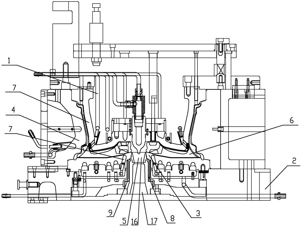
[0020] As shown in the figure, the present invention provides a water-cooled hub mold, including an upper mold 1, a lower mold 3, a side mold 4, a base 2, a sprue 5, a product 6 and a high-pressure water cooling device, the upper mold 1, the lower mold 3 and the side mold 4 are combined to form the casting cavity of the wheel hub to be cast, the lower mold 3 and the side mold 4 are fixed on the base 2, and the high-pressure water cooling device includes the upper end, the lower end and the side surface of the product 6 The cooling pipeline 7, the pouring port 5 is located at the bottom of the lower mold 3, and a heat preservation device for insulating the pouring port 5 is provided between the side of the pouring port 5 and the lower mold 3, and the heat preservation device refers to The lower mold 3 is provided with an annular groove 8 surroun...


PUM


Abstract

The invention discloses a water-cooled wheel hub mould. The water-cooled wheel hub mould comprises an upper mould (1), a lower mould (3), a side mould (4), a pedestal (2), a sprue gate (5), a product (6), and a high pressure water cooling device; a casting cavity of wheel hubs to be casted is formed via combination of the upper mould (1), the lower mould (3), and the side mould (4); the lower mould (3) and the side mould (4) are both fixed on the pedestal (2); the high pressure water cooling device comprises cooling pipelines (7) arranged on the upper end, the lower end, and the side surface of the product (6); the sprue gate (5) is arranged on the bottom of the lower mould (3); and a thermal insulation device used for thermal insulation of the sprue gate (5) is arranged between the side surface of the sprue gate (5) and the lower mould (3). The water-cooled wheel hub mould is high in cooling speed, and is capable of realizing progressive solidification, reducing casting rejection rate, and increasing production efficiency.

Description

technical field [0001] The invention relates to the technical field of mechanical casting, in particular to a water-cooled hub mold. Background technique [0002] As one of the most important moving parts of a car, the wheel hub has high requirements on its performance, weight and service life. At present, aluminum alloy wheels stand out in the automotive industry for their light weight, fast heat dissipation, good shock absorption performance, long life, and good balance. [0003] Aluminum alloy wheels are generally produced by casting. The molds for casting wheels mainly include upper molds, lower molds, side molds and bases. After the upper molds, lower molds and side molds are combined, the casting molds of the wheels to be cast are formed. The cavity, the lower mold and the side molds are all fixed on the base. During casting, the cavity is filled with material from the sprue located on the lower mold. During the solidification process after pouring, the area formed a...

Claims


Application Information

Patent Timeline
Patent Type & Authority Applications(China)
IPC IPC(8): B22C9/28B22C9/08B22D27/04
Inventor 何灿东陈木星刘建高
Owner 佛山市灿东模具技术有限公司
Why Eureka
Try Eureka