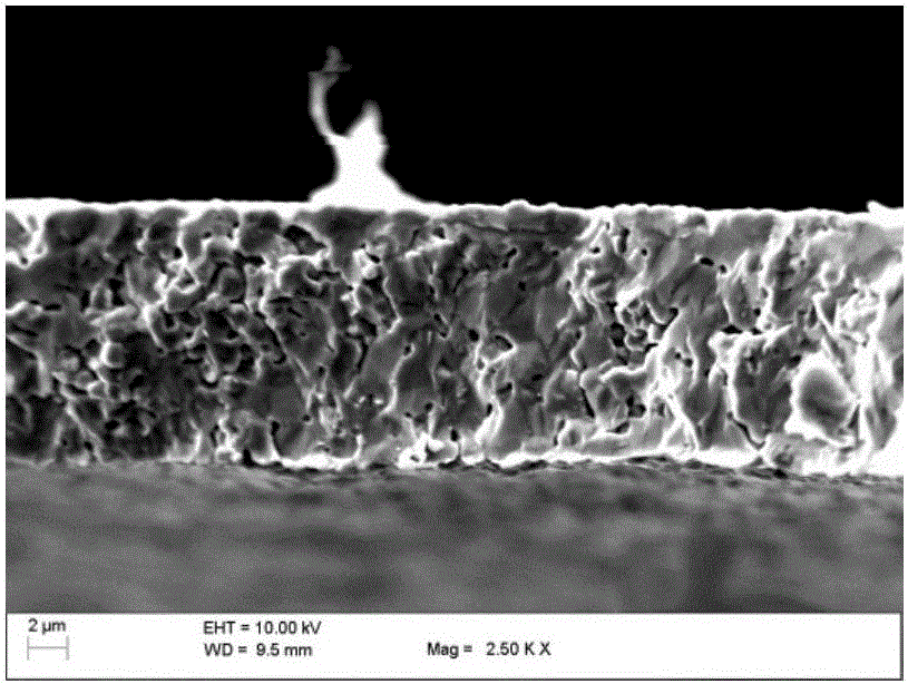
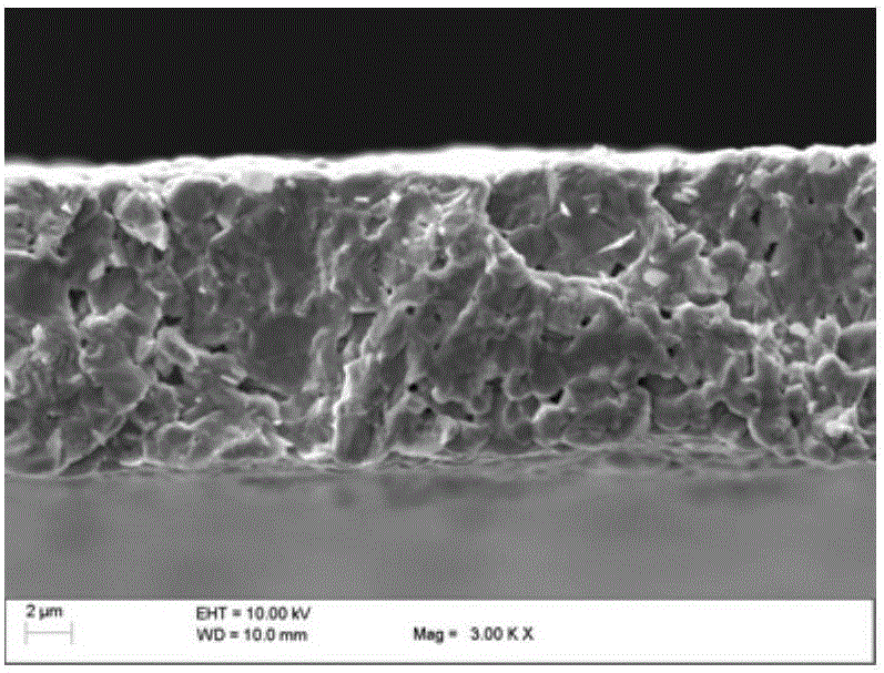
MnCoNi oxide ceramic infrared sensitive element densifying method

An oxide ceramic and densification technology, applied in the field of infrared detectors, can solve problems such as poor mechanical strength, increased detector noise, voids, etc., to achieve improved electrical performance qualification rate, reduced internal damage, and good process stability. Effect

Active Publication Date: 2015-10-28
BEIJING INST OF CONTROL ENG
View PDF3 Cites 2 Cited by
  • Summary
  • Abstract
  • Description
  • Claims
  • Application Information

AI Technical Summary

Problems solved by technology

Its minimum width is only 0.13mm, and its thickness is only 10μm. Due to its small size and thin thickness, its mechanical strength is usually poor
[0003] The current sheet pressing process is difficult to ensure the compactness, only the upper and lower sides are pressed, and the other directions are not restricted, causing the sheet to expand along the plane direction, resulting in poor compactness of the green body after forming, and there are dimensions between the edge and the center of the green body Problems such as inconsistent thickness and density, and easy to cause defects such as cracks and voids inside the sheet
The above-mentioned defects usually exist inside the thin slice, and it is difficult to remove them by optical inspection, which is a potential hidden danger that causes the noise of the detector to increase
At present, there is no fully suitable method for densification of the sensitive element of the infrared detector

Method used


Image

  • MnCoNi oxide ceramic infrared sensitive element densifying method
  • MnCoNi oxide ceramic infrared sensitive element densifying method
  • MnCoNi oxide ceramic infrared sensitive element densifying method

Examples


Embodiment 1

[0058] Embodiment 1 (width is the sensitive element flake of 130 μm)

[0059] Concrete implementation steps of the present invention are as follows:

[0060] (1) Preparation of sensitive element flakes:

[0061] The first step is to prepare MnCoNi oxide powder according to the MnCoNi atomic ratio of 52:32:16, and spread the powder evenly between two plexiglass plates to form a circular area of ​​about Φ5cm~8cm;

[0062] In the second step, place the above-mentioned double-layer plexiglass plate in the hydraulic press, and keep the pressure for 10s after the pressure reaches 15±0.1MPa;

[0063] The third step is to open the plexiglass plate after the pressure is removed from the hydraulic press, and gently sweep the pressed sheet from the plexiglass plate onto the glass plate with a small brush, and use a measuring microscope equipped with a special blade holder to cut the sheet with a special blade It is a strip with a width of 0.17mm to 0.20mm and a length of not less than ...

Embodiment 2

[0102] Embodiment 2 (width is the sensitive element sheet of 300 μm)

[0103] Concrete implementation steps of the present invention are as follows:

[0104] (1) Preparation of sensitive element flakes:

[0105] The first step is to prepare MnCoNi oxide powder according to the MnCoNi atomic ratio of 52:32:16, and spread the powder evenly between two plexiglass plates to form a circular area of ​​about Φ5cm~8cm;

[0106] In the second step, place the above-mentioned double-layer plexiglass plate in the hydraulic press, and keep the pressure for 10s after the pressure reaches 15±0.1MPa;

[0107] The third step is to open the plexiglass plate after the pressure is removed from the hydraulic press, and gently sweep the pressed sheet from the plexiglass plate onto the glass plate with a small brush, and use a measuring microscope equipped with a special blade holder to cut the sheet with a special blade It is a strip with a width of 0.38mm to 0.43mm and a length of not less than ...


PUM

PropertyMeasurementUnit
porosityaaaaaaaaaa
porosityaaaaaaaaaa

Abstract

The invention discloses a MnCoNi oxide ceramic infrared sensitive element densifying method. According to the method, firstly, an infrared sensitive element slice to be treated is fixed through a pressing plate; secondly, the infrared sensitive element slice to be treated is placed in a graphite furnace; a densified infrared sensitive element slice can be obtained by controlling pressure and the temperature increasing speed; through verification, the obtained infrared sensitive element slice is low in porosity, and the noise and resistance value yield is high.

Description

technical field [0001] The invention relates to a densification method suitable for infrared detectors, especially for infrared sensitive elements—MnCoNi oxide ceramic thin slices. Background technique [0002] The infrared detector is mainly used in the satellite attitude control subsystem to capture the earth's CO 2 Layer long-wave infrared signal and realize the conversion of photoelectric signal. The sensitive element of the infrared detector—the thermistor sheet is a semiconductor ceramic sheet with a negative temperature coefficient of resistance composed of oxides of Mn, Co, and Ni. First, the powder material is prepared by chemical reaction and physical grinding, and then the sheet is Made by pressing, sintering, cutting and other processes. Its minimum width is only 0.13 mm and its thickness is only 10 μm. Due to its small size and thin thickness, its mechanical strength is usually poor. [0003] The current sheet pressing process is difficult to ensure the compa...

Claims


Application Information

Patent Timeline
Patent Type & Authority Applications(China)
IPC IPC(8): C04B35/622C04B35/01
Inventor 徐庆安李慧邵逸恺孟庆红吕志强常玲玲庄建文贾文娇田广袁鸣
Owner BEIJING INST OF CONTROL ENG
Why Eureka
Try Eureka