Energization wire combustion experiment device capable of automatically igniting and collecting smoke and method

A technology of automatic ignition and experimental equipment, applied in the direction of sampling equipment, chemical analysis by combustion, etc., can solve the problems of manual operation, inability to obtain wire fire dynamic flame smoke particles, flame interference, etc.

Active Publication Date: 2015-10-28
UNIV OF SCI & TECH OF CHINA
View PDF9 Cites 11 Cited by
  • Summary
  • Abstract
  • Description
  • Claims
  • Application Information

AI Technical Summary

Problems solved by technology

[0004] In fire detection technology, smoke particles are an important criterion for fire diagnosis. However, the existing smoke particle collection technology can only collect static flame smoke particles or smoke particles on the surface of smoldering objects, and cannot obtain the dynamic flame smoke of wire fire spread. particles
In the traditional thermophoresis collection method, the biofilm stays in the flame for a short time, and only transient smoke particles can be obtained, but the shape and distribution of smoke particles at different heights of the wire fire within a period of time cannot be obtained.
In addition, due to the small size of the wire flame, the existing smoke particle collection method is likely to cause interference to the flame while collecting smoke
Experimental devices for studying the combustion of energized wires of aviation and spacecraft often need to work in equipment that simulates related environments (such as low pressure cabins, drop towers, aviation and spacecraft, etc.), and their internal space is limited and cannot be manually operated. Methods of collecting smoke particles and ignition are not applicable

Method used


Image

  • Energization wire combustion experiment device capable of automatically igniting and collecting smoke and method
  • Energization wire combustion experiment device capable of automatically igniting and collecting smoke and method
  • Energization wire combustion experiment device capable of automatically igniting and collecting smoke and method

Examples


specific Embodiment

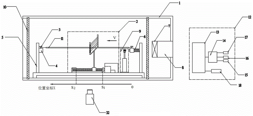
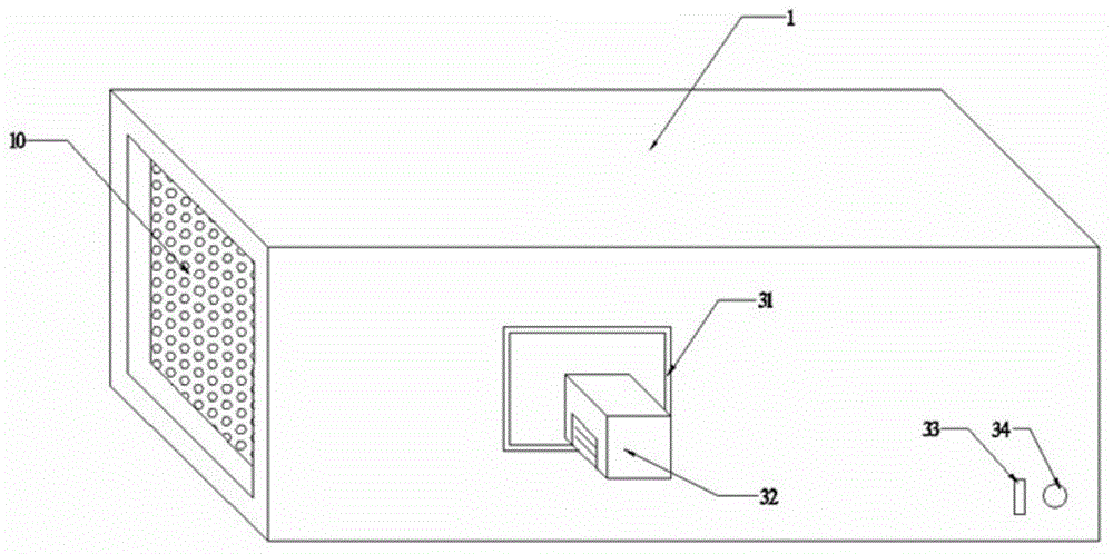
[0061] Such as figure 1 and figure 2 As shown, the present invention includes a combustion chamber 1 and a control center 12 in two parts. The combustion chamber 1 includes a sample table 5, an automatic smoke particle collection device 2, an automatic ignition device 9, and a forced convection generating device. The combustion chamber 1 is a cuboid with an opening at its left end, a circular air inlet on the right wall, a rectangular observation window 31 on the front wall, and a camera 32 fixed by the window for real-time monitoring of the combustion process of the sample wire 11; The lower corner is provided with a fan switch 33 and a wind speed adjustment knob 34 . The control center 12 is used to realize the automatic control of each device in the combustion chamber 1, and its hardware block diagram is as follows: Figure 5 Shown: the computer 13 is connected with the camera 32; the computer 13 is connected with the single-chip microcomputer 14, and the three interfac...


PUM


Abstract

The invention discloses an energization wire combustion experiment device capable of automatically igniting and collecting smoke and a method. The device comprises two parts of a combustion chamber and a control center; a sample platform is arranged in the combustion chamber, the middle of the sample platform is provided with an automatic smoke particle collecting device, one end of the sample platform is provided with an automatic igniting device, a sample wire is fixed on the sample platform, and a control circuit of the sample wire is connected with a relay; the two ends of the combustion chamber are provided with forced convection generation devices, the combustion chamber is a cuboid, an opening is formed in the left end of the combustion chamber, a circular air inlet is formed in the right wall face, a draught fan is arranged at the circular air inlet, the front wall face of the combustion chamber is provided with a rectangular observation window, a camera is fixed at the edge of the window, and the lower right corner of the front wall face of the combustion chamber is provided with a draught fan switch and an air speed adjusting knob. According to the device and the method, the shape and distribution of smoke particles at different height of dynamic flames in the fire spreading process can be obtained, and cable fires can be detected and prevented in time.

Description

technical field [0001] The invention relates to a live wire combustion experiment device suitable for simulating the environment of aerospace vehicles, in particular to a live wire combustion test device and method capable of automatic ignition and smoke collection. Background technique [0002] Conductor fire is the main cause of household conventional electrical fires and aerospace fires. Studying the shape and distribution of smoke particles, flame propagation rate, flame shape, and flame temperature of wire combustion is of great significance to the development of cable fire safety theory and prevention technology. . [0003] The existing wire combustion experiment device usually includes a combustion chamber, a sample stage, an ignition device, a forced convection generating device and an image acquisition device. The forced convection generating device includes a fan, a ventilation duct and an equalizer. The ignition device is an electric heating wire coil ignition. ...

Claims


Application Information

Patent Timeline
Patent Type & Authority Applications(China)
IPC IPC(8): G01N1/22G01N31/12
Inventor 张永明赵路遥王晓伟何豪方俊王进军
Owner UNIV OF SCI & TECH OF CHINA
Why Eureka
Try Eureka