Optical fiber transmission lighting device
A lighting device and optical fiber transmission technology, which is applied to lighting devices, fixed lighting devices, components of lighting devices, etc., can solve the problems of high safety hazards, high energy consumption of outdoor lighting technology, troublesome detection and maintenance, etc., and achieve excellent energy saving effect. , The device has good safety performance and is convenient for inspection and maintenance.
- Summary
- Abstract
- Description
- Claims
- Application Information
AI Technical Summary
Problems solved by technology
Method used
Image

Examples
Embodiment 1
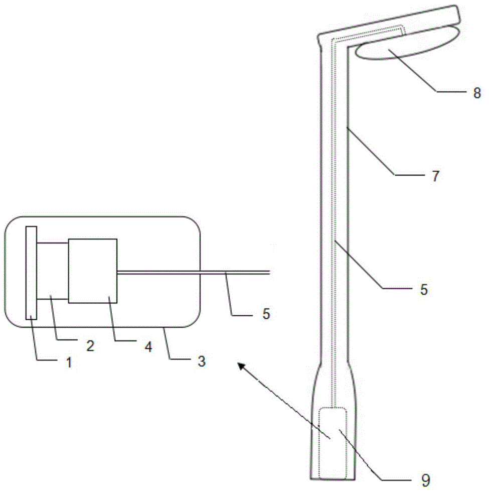
[0037] Such as figure 1 It is a schematic structural diagram of a single group of outdoor lighting devices, and the optical fiber coupling device 9 and the transmission optical fiber 5 are located in the lamp post 7; Figure 5 As shown, the laser headlight 8 includes a yellow phosphorus filter 82, a reflective bowl 83 and a laser beam expander 84. The parallel blue light enters the laser beam expander 84 of the laser headlight 8 after being output from the output terminal, and the blue laser light is evenly irradiated to On the yellow phosphorus filter 82, a part of the blue laser light reacts with the yellow phosphorus filter 82 to generate yellow light, and a part of the blue light is mixed with the yellow light generated by the excitation. The mixing ratio of blue and yellow light is 1:3, and the uniform output of high-efficiency white light Provide white light illumination for the road, and the remaining part of the blue laser light will be emitted to the reflective bowl 8...
Embodiment 2
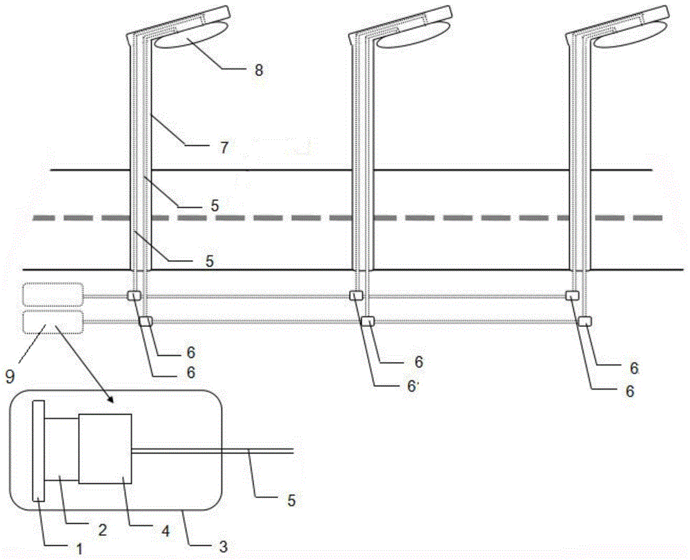
[0040] Such as figure 2It is a structural schematic diagram of multiple groups of outdoor lighting devices. High-power laser diodes 2 can be used to control street lights in series. The fiber coupling device 9 and part of the transmission fiber 5 are located outside the lamp post 7. The fiber coupling device 9 and the transmission fiber 5 are two corresponding groups. , the beam splitter 6 divides the laser beam into two beams, one beam is transmitted to the laser headlight 8 through the transmission fiber 5, and the other beam is transmitted to the next beam splitter for further splitting, and so on, the beam splitter 6 6W of laser energy needs to be separated to provide enough energy to meet the brightness requirements of outdoor lighting areas;
[0041] Such as Image 6 As shown, the laser headlight 8 includes two sets of reflectors 81, a yellow phosphorus filter 82 and a reflective bowl 83. The surface of the reflector 81 is coated with an all-dielectric reflective film ...
PUM
| Property | Measurement | Unit |
|---|---|---|
| Wavelength | aaaaa | aaaaa |
Abstract
Description
Claims
Application Information
 - R&D
- Intellectual Property
- Life Sciences
- Materials
- Tech Scout
- Unparalleled Data Quality
- Higher Quality Content
- 60% Fewer Hallucinations
Browse by: Latest US Patents, China's latest patents, Technical Efficacy Thesaurus, Application Domain, Technology Topic, Popular Technical Reports.
© 2025 PatSnap. All rights reserved.Legal|Privacy policy|Modern Slavery Act Transparency Statement|Sitemap|About US| Contact US: help@patsnap.com