Micro-fluidic chip heat dissipation device, and manufacturing method thereof

A technology of microfluidic chips and cooling devices, applied in the field of microfluidics, can solve the problems that cannot be realized, limit the application range and effect of chip materials, etc.

Active Publication Date: 2015-11-11
TECHNICAL INST OF PHYSICS & CHEMISTRY - CHINESE ACAD OF SCI
View PDF7 Cites 11 Cited by
  • Summary
  • Abstract
  • Description
  • Claims
  • Application Information

AI Technical Summary

Problems solved by technology

This method is convenient, fast, and conducive to chip integration, but the chip substrate material doped with high thermal conductivity materials will also change in terms of conductivity, wetting, electroosmosis, electrowetting, water permeability and air permeability, etc., to a large extent. Limit the application range and effect of the original chip material
In addition, the enhancement of heat transfer in the microfluidic chip by increasing the thermal conductivity of the chip material is also an overall temperature control method. If there are multiple small areas in the chip that need to be controlled independently to enhance heat transfer, this method cannot be realized.

Method used


Image

  • Micro-fluidic chip heat dissipation device, and manufacturing method thereof
  • Micro-fluidic chip heat dissipation device, and manufacturing method thereof
  • Micro-fluidic chip heat dissipation device, and manufacturing method thereof

Examples


Embodiment 1

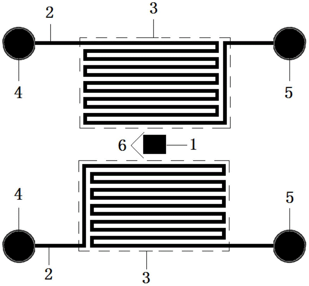
[0047] Such as figure 1 As shown, the present embodiment provides a cooling device for a microfluidic chip, including a heat generating region 1 and a microfluidic channel 2 with high thermal conductivity. In this embodiment, the heat generating region 1 is rectangular when viewed from top to bottom. High thermal conductivity micro-channels 2 are horizontally arranged in parallel in series (end-to-end connection of sub-channels), forming an enhanced heat transfer area 3 (first heat transfer area). The two enhanced heat transfer regions 3 are arranged symmetrically on both sides of the heat generating region 1. The enhanced heat transfer region 3 and the heat generating region 1 are at the same level and at the same height. The size is not greater than the width of the high thermal conductivity micro flow channel 2 . The heat dissipation device for the microfluidic chip provided in this embodiment facilitates conduction and diffusion of heat in the heat generating region 1 al...

Embodiment 2

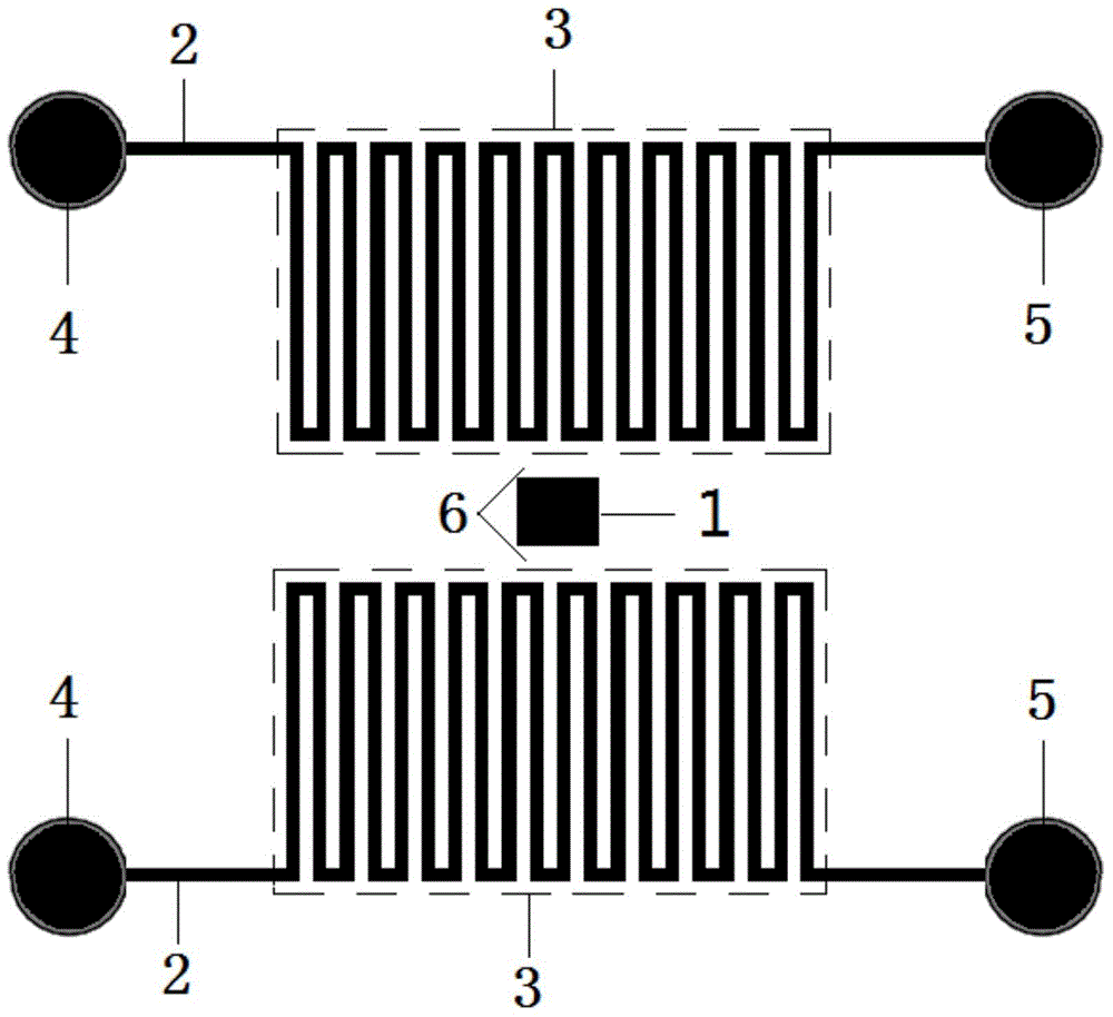
[0055] Such as figure 2 As shown, the microfluidic chip cooling device provided in this embodiment includes a heat generating region 1 and a high thermal conductivity microchannel 2 . In this embodiment, the heat generating region 1 is rectangular when viewed from top to bottom. The high thermal conductivity micro-channels 2 are vertically arranged in parallel and in series to form an enhanced heat transfer area 3 (first heat transfer area). The two enhanced heat transfer regions 3 are arranged symmetrically on both sides of the heat generating region 1, and the enhanced heat transfer region 3 is at the same level and at the same height as the heat generating region 1. ), the size of the gap is not greater than the width of the high thermal conductivity micro-channel 2 . The microfluidic chip cooling device provided in this embodiment facilitates the conduction and diffusion of heat in the heat generating region 1 along the vertical and horizontal directions. It should be ...

Embodiment 3

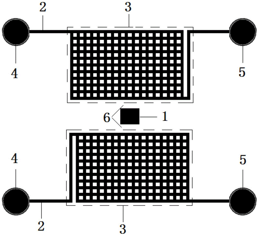
[0063] Such as image 3 As shown, the microfluidic chip cooling device provided in this embodiment includes a heat generating region 1 and a high thermal conductivity microchannel 2 . In this embodiment, the heat generating region 1 is rectangular when viewed from top to bottom. High thermal conductivity micro-channels 2 are vertically arranged in a staggered manner to form an enhanced heat transfer area 3 (third heat transfer area). Two enhanced heat transfer regions 3 are arranged symmetrically on both sides of the heat generating region 1, the enhanced heat transfer region 3 is at the same level and at the same height as the heat generating region 1, and at the same time, the two are separated by a gap formed by a micro-scale film 6. The size of the gap is not larger than the width of the high thermal conductivity micro flow channel 2 . It should be understood that image 3 The enhanced heat transfer area 3 can also be set to maintain a certain inclination angle (0-90°) ...


PUM


Abstract

The invention discloses a micro-fluidic chip heat dissipation device, and a manufacturing method thereof. The micro-fluidic chip heat dissipation device is used for heat dissipation of heat production areas of micro-fluidic chips, and comprises high thermal conductivity micro-channels filled with a high thermal conductivity liquid; and the high thermal conductivity micro-channels and the heat production areas are arranged with microscale intervals. Heat dissipation of the micro-fluidic chips is realized via the high thermal conductivity micro-channels filled with the high thermal conductivity liquid, and the micro-fluidic chip heat dissipation device is especially suitable for enhanced heat transferring of tiny areas in low thermal-conductivity micro-fluidic chips. When the temperature of the heat production areas is increased, the high thermal conductivity liquid near the heat production areas absorbs heat energy of the heat production areas, and transfers the heat energy to larger spaces in the micro-fluidic chips rapidly, and heat generated in the micro-fluidic chips can be eliminated naturally under chip surface natural convection action. The micro-fluidic chip heat dissipation device is simple in structure, is convenient to prepare, is low in cost, and is excellent in integration performance, and more importantly, it is convenient to realize anisotropism reinforcement of heat transferring of the tiny areas in the chips.

Description

technical field [0001] The invention belongs to the field of microfluidic technology, and more specifically relates to a microfluidic chip cooling device and a manufacturing method thereof. Background technique [0002] In microfluidic chip analysis, micro components (micro pumps, micro valves, micro mixers, micro separators, micro reactors, etc.) Usually accompanied by heat generation. This heat has a heating effect on the sample reagent microfluidics, raising the temperature of the microfluidics. If the sample reagent temperature rises and deviates from the ideal biochemical temperature, the efficiency of microfluidic analysis will decrease, or even fail. For example, in a microfluidic cell culture chip driven by high-voltage electroosmosis, significant current Joule heat will be generated between the positive and negative microelectrodes of the electroosmotic micropump, making the actual culture temperature of the cell fluid higher than the ideal culture temperature. H...

Claims


Application Information

Patent Timeline
Patent Type & Authority Applications(China)
IPC IPC(8): B01L7/00B01L3/00
Inventor 高猛桂林
Owner TECHNICAL INST OF PHYSICS & CHEMISTRY - CHINESE ACAD OF SCI
Why Eureka
Try Eureka