
Single-particle transient effect injection method based on substitution model

A single-event transient and surrogate model technology, applied in electronic circuit testing, measuring devices, instruments, etc., can solve problems such as dependence on accuracy and speed, high time overhead, and increased testing costs

Active Publication Date: 2015-11-11
CENT SOUTH UNIV
View PDF2 Cites 12 Cited by
  • Summary
  • Abstract
  • Description
  • Claims
  • Application Information

AI Technical Summary

Problems solved by technology

At present, the simulation of the SET effect is concentrated on the physical level and electrical level of the device. In terms of the physical layer simulation of the device, the traditional SET effect injection methods mainly include laser irradiation and heavy ion bombardment. Both of these methods require special testing equipment. Not only increases the cost of testing, but also changes the physical characteristics of the device under test, and may even cause damage to the device under test
The simulation method at the electrical layer mainly adopts the computer to carry out the damage simulation simulation and the field programmable gate array FPGA to realize the hardware acceleration method. The former mainly carries out the mechanism modeling of a single device, and the calculation process is complicated and depends on the accuracy and speed of the simulation software. The time overhead is relatively large; the latter's simulation of single-event transients is mostly concentrated in the storage unit of the hardware, which has certain limitations

Method used


Image

  • Single-particle transient effect injection method based on substitution model
  • Single-particle transient effect injection method based on substitution model
  • Single-particle transient effect injection method based on substitution model

Examples


Embodiment Construction

[0074] The embodiments of the present invention will be described in detail below with reference to the accompanying drawings, but the present invention can be implemented in many different ways defined and covered by the claims.

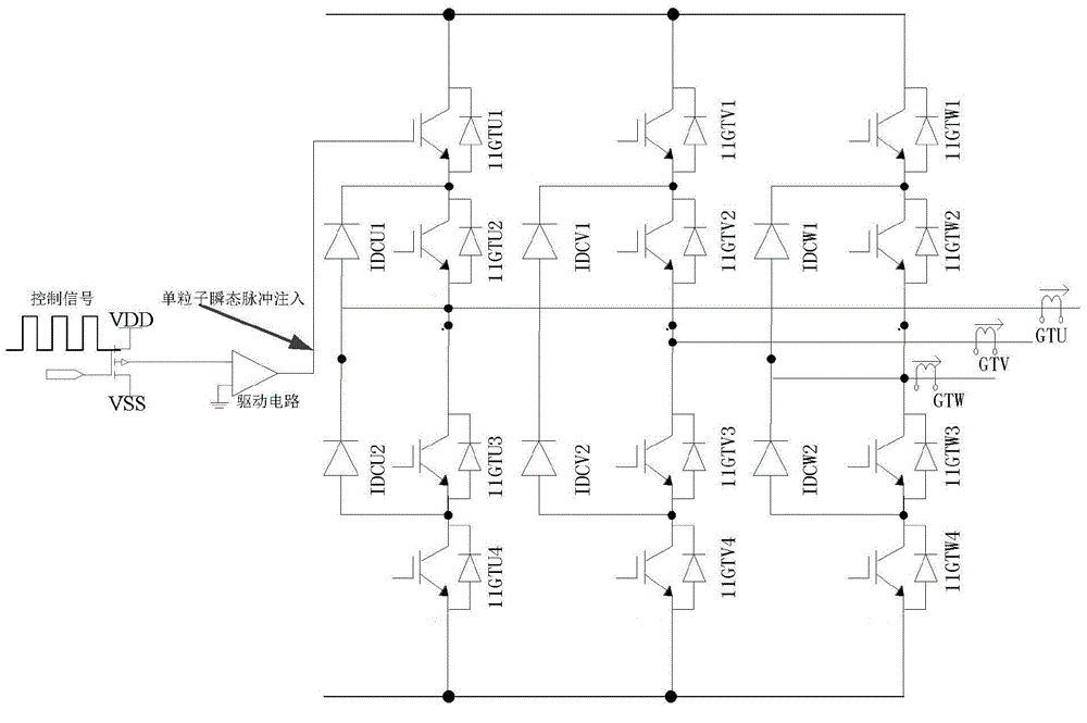
[0075] Specific embodiments of the present invention will be described below in conjunction with the accompanying drawings. figure 1 It is a schematic diagram of the tested circuit adopted in the present embodiment. This tested circuit adopts the scheme of two power switching devices connected in series and the middle point band clamp diode, and adopts the voltage vector modulation control (SVPWM) strategy to control; and through the binary digital pulse Signals "0" and "1" control the power device and have a corresponding drive circuit. When the drive level is not reached, the power device cannot be turned on.

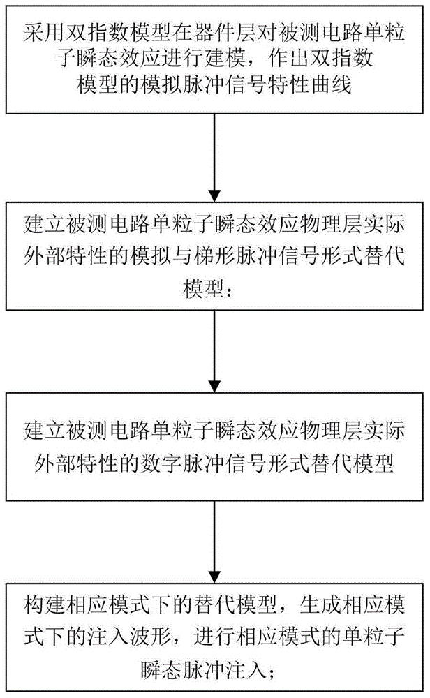
[0076] Such as figure 2 As shown, the single event transient effect injection method based on the surrogate model includes the following...


PUM


Abstract

The invention discloses a single-particle transient effect injection method based on a substitution model. The method includes modeling single-particle transient effect of a circuit to be detected on a device layer with a bi-index model, respectively establishing analog pulse signal formed, trapezoid pulse signal formed and digital pulse signal formed substitution models for actual external physical layer characteristics of single-particle transient effect of the circuit to be detected, constructing substitution models for actual external physical layer characteristics of single-particle transient effect of the circuit to be detected under corresponding models by setting analog, trapezoid or digital pulse signal injection models, generating injection waveforms under corresponding modes, and completing injection of single-particle transient pulse under different modes. No special device is needed, the physical characteristics of a device / circuit to be detected remain unchanged, and injection of different expression forms of single-particle transient effect for single device and circuit structure can be completed. A real and reliable fault simulating environment can be provided for researching circuit reinforcing technology, real-time fault diagnosis, and isolation and fault tolerance technology.

Description

technical field [0001] The invention relates to a single particle transient effect injection method based on a substitution model, belonging to the fields of circuit fault injection, signal processing and the like. Background technique [0002] After the high-energy particles are incident on the semiconductor material, the target material will be ionized, and charges will be accumulated on the incident trajectory. The transient pulse generated by the charged particles will affect the output of the next-level circuit, resulting in system dysfunction and transient changes in the electrical performance of the device. The phenomenon is called single event transient effect (singleeventtransient, SET). As circuit technology enters the deep submicron era, small size and low voltage make circuit nodes more sensitive to electromagnetic interference in the working environment and the impact of high-energy particles, resulting in more and more serious single-event transient effects. De...

Claims


Application Information

Patent Timeline
IPC IPC(8): G01R31/00G01R31/28
Inventor 阳春华杨笑悦彭涛杨超赵帅史露尹进田
Owner CENT SOUTH UNIV
Learn More