
Hydrogen peroxide low-temperature vaporization sterilization device and method

A hydrogen peroxide and sterilization device technology, which is applied in the field of hydrogen peroxide low-temperature vaporization sterilization device, can solve the problems of complex control system of the device, long disinfection and sterilization cycle, and reduced sterilization efficiency, and achieve good air mass diffusivity, Effect of small increase in temperature and relative humidity and reduced corrosiveness

Inactive Publication Date: 2015-11-18
深圳市图永医药科技有限公司
View PDF0 Cites 2 Cited by
  • Summary
  • Abstract
  • Description
  • Claims
  • Application Information

AI Technical Summary

Problems solved by technology

[0003] The so-called spray method is to use compressed air or a jet pump to spray hydrogen peroxide into small droplets and spread them into the space to be sterilized to achieve the purpose of sterilization; Slow diffusion, easy sedimentation, uneven distribution, long disinfection and sterilization cycle, and poor sterilization effect
[0004] The high-temperature flash vaporization method is to drip or spray hydrogen peroxide (vaporization temperature around 140-150°C) in the form of small droplets onto the high-temperature flash evaporation plate (120-160°C) and use the airflow generated by the blower and Negative pressure vacuum vaporizes hydrogen peroxide and blows it into the space to be sterilized for sterilization; but high temperature makes hydrogen peroxide (H 2 o 2 ) a large amount of decomposition loss (decomposed into water and oxygen 2H 2 o 2 →2H 2 O+O 2 , lose the sterilizing effect, in order to achieve the sterilizing effect, the amount of hydrogen peroxide must be increased), the sterilizing efficiency is reduced, the ambient humidity rises rapidly, and hydrogen peroxide condenses, resulting in sterilization failure and corrosiveness, and greater energy consumption. At the same time, the control system of the device using this method is complex and expensive, and sometimes it is required to add a wheel dehumidification device to the air conditioning system of the space to be sterilized.

Method used


Image

  • Hydrogen peroxide low-temperature vaporization sterilization device and method

Examples


Embodiment Construction

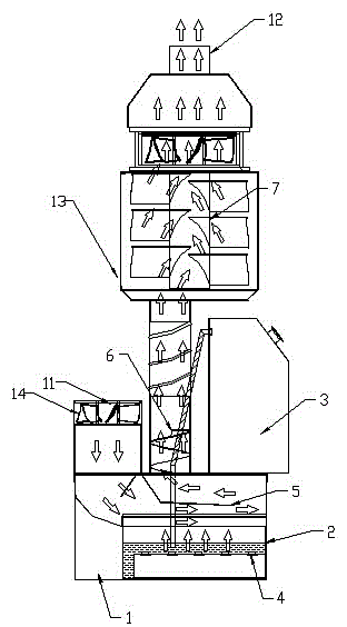
[0021] see figure 1 As shown, a hydrogen peroxide low-temperature vaporization sterilization device includes a main box body 1, and a hydrogen peroxide supply device is arranged in the main box body 1, and the hydrogen peroxide supply device includes a The hydrogen peroxide vaporization tank 2 inside 1 and the hydrogen peroxide liquid storage bottle 3 arranged outside the main box body 1 use the principle of the connector to make the hydrogen peroxide liquid storage bottle 3 flow to the hydrogen peroxide vaporization tank inside the main box body 1 2. Replenish hydrogen peroxide in real time and keep the liquid level constant to ensure the constant vaporization rate; the hydrogen peroxide vaporization tank of the hydrogen peroxide supply device is provided with a blasting water column device, and the blasting water column device is a high High-frequency resonant vibrating piece 4, high-frequency resonant vibrating piece 4 makes the hydrogen peroxide solution produce a 1-20 μm ...


PUM


Abstract

The invention relates to a hydrogen peroxide low-temperature vaporization sterilization device, which comprises a main box body, wherein a hydrogen peroxide supply device is arranged in the main box body, and the device comprises a hydrogen peroxide liquid storage bottle and a hydrogen peroxide vaporization tank; a blasting water column device is arranged inside the hydrogen peroxide vaporization tank; by virtue of the blasting water column device, a hydrogen peroxide gas-liquid mixture is formed by a hydrogen peroxide solution; a gas-liquid separation device is arranged above the hydrogen peroxide vaporization tank; by virtue of the gas-liquid separation device, knockout occurs as the hydrogen peroxide gas-liquid mixture is blocked, so that the gas-liquid mixture is separated into hydrogen peroxide gas and hydrogen peroxide liquid drop, and the hydrogen peroxide liquid drop flows back into the vaporization tank.

Description

technical field [0001] The invention relates to the field of space disinfection in pharmaceutical enterprises, hospitals, public places, vehicles, families, etc., in particular to a hydrogen peroxide low-temperature vaporization sterilization device. Background technique [0002] Hydrogen peroxide (commonly known as hydrogen peroxide) is a commonly used disinfectant. It has a strong sterilization effect after vaporization (more than 300 times stronger than liquid state), and can be used for space disinfection / sterilization. Existing hydrogen peroxide vaporization sterilization devices generally use spraying and high-temperature flash vaporization methods to realize the vaporization of hydrogen peroxide. [0003] The so-called spray method is to use compressed air or a jet pump to spray hydrogen peroxide into small droplets and spread them into the space to be sterilized to achieve the purpose of sterilization; Diffusion is slow, easy to settle, uneven distribution, long dis...

Claims


Application Information

Patent Timeline
Patent Type & Authority Applications(China)
IPC IPC(8): A61L2/20A61L2/24
Inventor 叶开学
Owner 深圳市图永医药科技有限公司
Learn More