Eureka AIR delivers breakthrough ideas for toughest innovation challenges, trusted by R&D personnel around the world.

Stimulated raman scattering suppression device, method and distributed optical fiber sensing system

A technology of stimulated Raman scattering and suppression device, applied in the field of optical sensing, can solve the problems of high cost, poor effect, complex structure, etc., to suppress stimulated Raman scattering, improve the signal-to-noise ratio of the system, and improve the system The effect of the signal-to-noise ratio

Inactive Publication Date: 2015-11-18
深圳市迅捷光通科技有限公司
View PDF20 Cites 2 Cited by
  • Summary
  • Abstract
  • Description
  • Claims
  • Application Information

AI Technical Summary

Problems solved by technology

[0005] The technical problem to be solved by the present invention is to provide a stimulated Raman scattering suppression device and method and a distributed optical fiber sensing system in view of the above-mentioned defects of the prior art such as complex structure, poor effect and high cost

Method used


Image

  • Stimulated raman scattering suppression device, method and distributed optical fiber sensing system
  • Stimulated raman scattering suppression device, method and distributed optical fiber sensing system
  • Stimulated raman scattering suppression device, method and distributed optical fiber sensing system

Examples


Embodiment Construction

[0033] In order to have a clearer understanding of the technical features, purposes and effects of the present invention, the specific implementation manners of the present invention will now be described in detail with reference to the accompanying drawings.

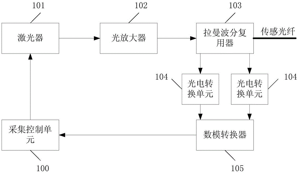
[0034] The stimulated Raman scattering suppression device can be used to improve the laser transmission efficiency, and its application to the distributed optical fiber sensing system will be introduced in detail below. First, a brief introduction to the conventional distributed optical fiber sensing system in the prior art, refer to figure 1 , figure 1 It is a schematic diagram of the structure of a conventional distributed optical fiber sensing system. Its working process is as follows: when the acquisition starts, the acquisition control unit 100 controls the laser 101 to emit laser pulses, which are input to the Raman wavelength division multiplexer 103 after passing through the optical amplifier 101, and output to...


PUM


Abstract

The invention relates to a stimulated raman scattering suppression device, a stimulated raman scattering suppression method and a distributed optical fiber sensing system. The stimulated raman scattering suppression device includes a master laser which is used for outputting master laser pulses, a slave laser which is used for outputting slave laser pulses for suppressing stimulated raman scattering of the master laser pulses in a sensing optical fiber so as to decrease the stimulated raman scattering threshold value of the sensing system, and a wave-combining wavelength division multiplexer which is used for performing wave combining processing on the master laser pulses and the slave laser pulses and outputting processing results to the sensing optical fiber. According to the stimulated raman scattering suppression device of the invention, the slave laser can suppress the stimulated raman scattering of the master laser pulses, so that the stimulated raman scattering threshold value of the sensing system can be improved, and the signal to noise ratio of the system can be improved; the slave laser is selected to be located on the second raman frequency shift point of the master laser, and therefore, the increase of the stimulated raman scattering of the second raman frequency shift point can be suppressed, and at the same time, the increase of the stimulated raman scattering of a first raman frequency shift point can be also suppressed, and therefore, the stimulated raman scattering threshold value can be further improved. The stimulated raman scattering suppression device is simple in structure and can effectively suppress the stimulated raman scattering and improve the signal to noise ratio.

Description

technical field [0001] The invention relates to the field of optical sensing, in particular to a stimulated Raman scattering suppression device and method and a distributed optical fiber sensing system. Background technique [0002] The distributed optical fiber temperature measurement sensor system is a temperature measurement system based on the OTDR principle with optical fiber as the sensing element. With its passive, intrinsically safe, quantitative temperature measurement, it is insensitive to electromagnetic interference and has a low false alarm rate. With the advantages of long service life and low maintenance cost, it is more and more widely used in fire alarm detection and temperature detection. In many practical applications, people have put forward higher and higher requirements for the performance of distributed optical fiber temperature measurement: the measurement distance is getting longer and the response time is getting faster, or the length of the detecti...

Claims


Application Information

Patent Timeline
Patent Type & Authority Applications(China)
IPC IPC(8): G01K11/32G01K11/324
Inventor 郑华明陈建成
Owner 深圳市迅捷光通科技有限公司
Why Eureka
Eureka Blog
Learn More