
Argon ion polishing/scanning electron microscope analyzing and sampling method for shale samples

An argon ion polishing and scanning electron microscope technology, applied in the field of petroleum geology, can solve the problems of inability to analyze shale samples, difficult to obtain bulk samples, easy to break, etc., to improve the success rate of sample preparation, facilitate cutting operations, and reduce cutting times. Effect

Inactive Publication Date: 2015-11-18
CHINA PETROLEUM & CHEM CORP
View PDF3 Cites 14 Cited by
  • Summary
  • Abstract
  • Description
  • Claims
  • Application Information

AI Technical Summary

Problems solved by technology

However, due to the well-developed bedding or fractures of the shale core samples taken, they are easily broken during cutting due to the vibration of the cutting blade and the erosion of cooling water, and it is difficult to obtain a block sample with a suitable size for polishing; or the actual drilling process Coring operations were not performed in the shale, resulting in only small rock chip samples available for analysis, but it is difficult to cut them fixedly, so it is impossible to perform argon ion polishing / SEM analysis on the above-mentioned types of shale samples to obtain these samples. The formation microscopic information corresponding to the sample

Method used


Image

  • Argon ion polishing/scanning electron microscope analyzing and sampling method for shale samples
  • Argon ion polishing/scanning electron microscope analyzing and sampling method for shale samples

Examples


Embodiment 1

[0020] Example 1 Argon ion polishing / scanning electron microscope sample preparation of brittle shale core samples

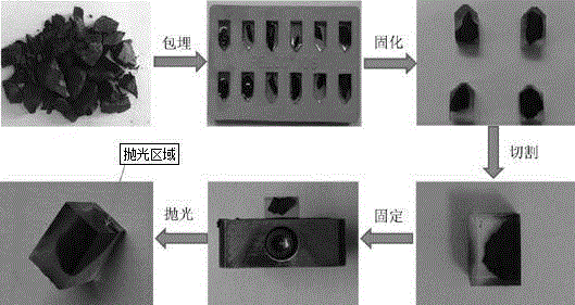
[0021] Such as figure 2 As shown, the steps of argon ion polishing / scanning electron microscope sample preparation for friable shale core samples are as follows:

[0022] (1) Embedding: Mix the embedding agent Eponate12 according to the ratio of resin monomer / DDSA / NMA / DMP-30=1 / 0.2 / 0.49 / 0.01, and remove air bubbles for later use. Place the shale sample in the embedding plate, slowly add the prepared embedding agent, and remove all air bubbles.

[0023] (2) Curing: The embedding plate embedded with the shale core sample was placed in an oven and cured at 60°C for 24 hours.

[0024] (3) Cutting: Take out the solidified shale core embedding sample from the embedding plate, cut it into a regular cuboid shape with a precision slicer, and ensure that the polished section of the shale sample is exposed.

[0025] (4) Polishing: stick the cut shale core embedded sampl...

Embodiment 2

[0026] Example 2 Argon ion polishing / scanning electron microscope sample preparation of shale cuttings samples

[0027] The steps of argon ion polishing / scanning electron microscopy sample preparation of shale cuttings samples are as follows:

[0028] (1) Embedding: Mix the embedding agent Eponate12 according to the ratio of resin monomer / DDSA / NMA / DMP-30=1 / 0.1 / 0.59 / 0.01, and remove air bubbles for later use. Place the shale sample in the embedding plate, slowly add the prepared embedding agent, and remove all air bubbles.

[0029] (2) Curing: The embedding plate embedded with the shale cuttings sample was placed in an oven and cured at 60°C for 16 hours.

[0030] (3) Cutting: Take the solidified shale cuttings embedded sample out of the embedding plate, place it in a precision microtome, cut it into a regular cuboid shape, and ensure that the polished section of the shale sample is exposed.

[0031] (4) Polishing: stick the cut shale cuttings embedding samples on the baffle,...


PUM


Abstract

The invention discloses an argon ion polishing / scanning electron microscope analyzing and sampling method for shale samples including fragile shale core samples and rock debris samples. The method comprises steps of embedding, curing, cutting and polishing. By comparison with a traditional argon ion polishing / scanning electron microscope analyzing and sampling method, the analysis range of the samples is widened with the method, the shale core samples which are fragile in the cutting and sampling processes and the shale rock debris samples with smaller sizes can be analyzed, and meanwhile, the success rate of sampling is increased.

Description

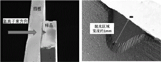
technical field [0001] The invention relates to the field of petroleum geology, in particular to an argon ion polishing / scanning electron microscope sample preparation method for shale samples. Background technique [0002] Scanning electron microscopy is an important analysis and research tool in the petroleum geology industry. Combined with argon ion polishing technology, it can reveal the real microstructure inside shale, especially a large number of nanoscale to micron-scale pores. These pores are crucial for studying the occurrence state of shale gas and the later development process. Before performing argon ion polishing on the shale sample, the shale sample needs to be cut into a suitable size (generally 10mm×10mm×3mm), and then placed on the baffle and polished with argon ion beam, such as figure 1 shown. [0003] Therefore, the shale samples used for argon ion polishing / SEM analysis must meet a certain size, generally a core sample, and not easily broken during th...

Claims


Application Information

Patent Timeline
Patent Type & Authority Applications(China)
IPC IPC(8): G01N1/28G01N1/44G01N1/32
Inventor 王亮程秀梅程伟曹海虹
Owner CHINA PETROLEUM & CHEM CORP
Learn More