Spray pipe for high-temperature diffusion furnace and application thereof

A technology of high-temperature diffusion and spray pipes, which is applied in the field of spray pipes, can solve problems such as the inability to adjust and improve the size and uniformity of the sheet resistance, the large difference in the size of the sheet resistance of the diffusion layer, and the inability to control the thickness of dead settling well. Achieve the effect of eliminating the short board effect, maintaining the uniformity in the silicon wafer, and good uniformity in the silicon wafer

Inactive Publication Date: 2015-11-18
ALTUSVIA ENERGY TAICANG
View PDF6 Cites 2 Cited by
  • Summary
  • Abstract
  • Description
  • Claims
  • Application Information

AI Technical Summary

Problems solved by technology

Of these two air intake methods, the first one only uses the tail air intake. When the phosphorus source is brought into the quartz tube by the source-carrying nitrogen gas, it is first absorbed by the silicon wafer at the end of the furnace, and then gradually diffuses towards the furnace mouth, so that The probability of silicon wafers at the intake end absorbing phosphorus sources is much greater than that of silicon wafers far away from the intake end. Under the same conditions of other process parameters, the difference in the square resistance of the diffusion layer between the silicon wafers in the furnace tube will inevitably be relatively small. Big
The second type adopts the structure of tail air intake and spray pipe air intake. This structure makes a part of the phosphorus source pass into the diffusion furnace tube through the tail intake pipe, and the other part enters the furnace tube through the spray pipe, and the phosphorus source enters through the spray pipe. The phosphorus source will directly reach the position in the diffusion furnace and the furnace mouth, which is indeed beneficial to eliminate the difference in square resistance between the sheets in the diffusion furnace tube, but due to the direction of the airflow ejected from the spray pipe and the flow from the tail intake pipe The direction of the airflow in the furnace is inconsistent, which will cause the airflow in the diffusion furnace tube to be turbulent. Therefore, although this method can improve the difference between the square resistance pieces and the pieces after the diffusion of the entire group of silicon wafers in the furnace tube, it will make the difference between each silicon piece. internal homogeneity
[0004] Therefore, these two air intake methods have their own limitations in increasing the size and uniformity of the diffused silicon wafer's square resistance, which makes it impossible to increase the diffused square resistance of the entire group of silicon wafers in the furnace tube through the adjustment of process parameters. The size and uniformity also lead to the inability to control the dead thickness of the front surface of the entire group of silicon wafers, which restricts the further improvement of the battery's electrical performance

Method used


Image

  • Spray pipe for high-temperature diffusion furnace and application thereof
  • Spray pipe for high-temperature diffusion furnace and application thereof
  • Spray pipe for high-temperature diffusion furnace and application thereof

Examples


Embodiment 1

[0032] An application example of the gas diffusion spray pipe prepared in the present invention, using P-type 156 monocrystalline silicon wafer as the base material, the specific steps of the use method are as follows:

[0033] (1) Make 800 P-type 156 monocrystalline silicon wafers into texturing;

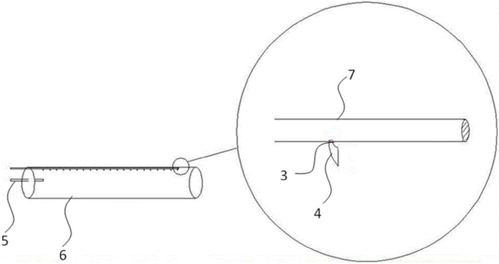
[0034] (2) Diffusing the monocrystalline silicon wafers in a tube diffusion furnace; divide the 156 monocrystalline silicon wafers into 2 groups, each with 400 wafers, among which group A will be diffused with a conventional tail gas diffusion furnace tube, and B The team used the diffusion furnace tube with tail gas inlet and gas diffusion spray tube in the present invention (take n=1, and its structure diagram is as figure 2 (Shown) perform diffusion. After this step, samples are taken in two groups to measure the sheet resistance of the silicon wafer after diffusion;

[0035] (3) Wet etch the silicon wafer after diffusion and polish the back surface;

[0036] (4) Use aluminum oxide and...

Embodiment 2

[0047] An application example of the gas diffusion spray pipe prepared in the present invention, using P-type 156 monocrystalline silicon wafer as the base material, the specific steps of the use method are as follows:

[0048] (1) Texture 1000 P-type 156 monocrystalline silicon wafers;

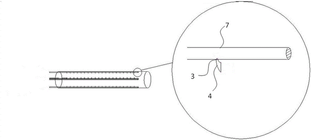
[0049] (2) Diffusing the monocrystalline silicon wafers in a tubular diffusion furnace; divide the 156 monocrystalline silicon wafers into 2 groups, 500 pieces in each group, among which group A uses the conventional tail air intake and spray air diffusion furnace The tube diffuses. Team B uses the diffusion furnace tube of the present invention with a tail air intake and a new spray tube (take n=4, and its structure diagram is as image 3 (Shown) perform diffusion. After this step, samples are taken in two groups to measure the sheet resistance of the silicon wafer after diffusion;

[0050] (3) Wet etch the silicon wafer after diffusion and polish the back surface;

[0051] (4) Use aluminum oxide an...


PUM


Abstract

The invention discloses a gas diffusion spray pipe. One end of the gas diffusion spray pipe is provided with a gas inlet, and the other end is a closed end. The spray pipe is provided with a spray opening which is communicated with a bent spray nozzle. The bent spray nozzle is provided with a bent part and a gas outlet. The inner diameter of the gas outlet is larger than the diameter of the spray opening. The gas outlet direction of the gas outlet is same with the gas inlet direction of the gas inlet of the spray pipe. The invention further discloses a high-temperature diffusion furnace with the gas diffusion spray pipe. The spraying direction of source nitrogen gas is changed. A phosphorus source is directly leaded to different positions of the diffusion furnace through the spray pipe. The source nitrogen gas can smoothly flow out from the novel spray pipe without turbulent flow. Incapability of a silicon wafer in a furnace pipe for sufficient reaction with the phosphorus source because of a position limitation is prevented.

Description

Technical field [0001] The invention relates to the field of crystalline silicon solar cell manufacturing, in particular to a spray tube used in a high-temperature diffusion furnace in a solar cell manufacturing process, which can improve the diffusion square resistance and its uniformity and its application. Background technique [0002] With the continuous development of the crystalline silicon solar cell manufacturing industry and the emergence of technologies such as passivation on the back of solar cells, the backside recombination of crystalline silicon solar cells is no longer a shortcoming restricting the improvement of solar cell conversion efficiency, but the front recombination has gradually become a solar cell. Obstacles to the improvement of battery conversion efficiency. It is undoubtedly one of the most direct and effective ways to reduce the front recombination of crystalline silicon solar cells to meet higher process requirements, and to increase the sheet resist...

Claims


Application Information

Patent Timeline
Patent Type & Authority Applications(China)
IPC IPC(8): H01L31/18
CPCH01L31/18Y02P70/50
Inventor 孙海平李静李洪波张斌
Owner ALTUSVIA ENERGY TAICANG
Why Eureka
Try Eureka