Dielectric dual-mode band-pass filter based on patch structure

A filter and dielectric resonator technology, applied in the field of dual-mode band-pass filters and dielectric dual-mode band-pass filters, can solve the problems of limited method and structure realization performance, difficult processing technology, complex structure, etc. Simple, reduced processing difficulty, high out-of-band rejection effect

Inactive Publication Date: 2015-11-18
SOUTH CHINA UNIV OF TECH
View PDF5 Cites 11 Cited by
  • Summary
  • Abstract
  • Description
  • Claims
  • Application Information

AI Technical Summary

Problems solved by technology

[0008] To sum up, the published dielectric multimode filter articles or patent documents mostly involve cutting corners or digging holes on the dielectric block. The proposed method and structure processing technology are difficult and costly, and the published dielectric multimode Filter articles or patent documents mostly involve single-cavity dielectric multimode filters with complex structures, which are not suitable for the design of multi-order multi-cavity high-performance filters, and the performance of the proposed method and structure is limited.

Method used


Image

  • Dielectric dual-mode band-pass filter based on patch structure
  • Dielectric dual-mode band-pass filter based on patch structure
  • Dielectric dual-mode band-pass filter based on patch structure

Examples


Embodiment 1

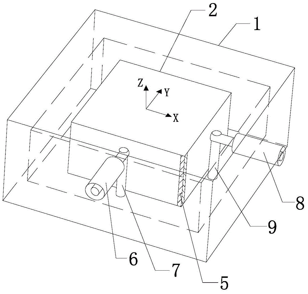
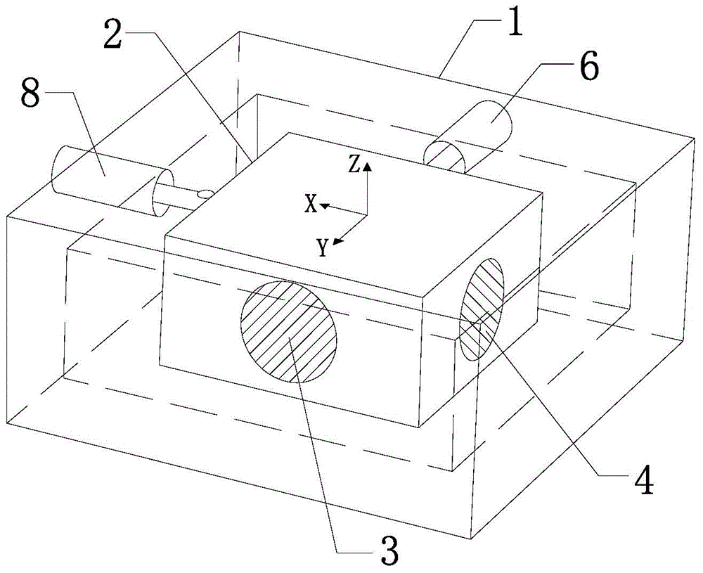
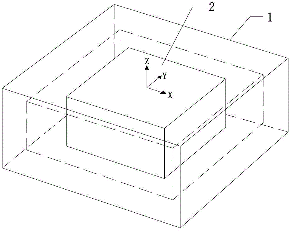
[0058] like figure 1 and figure 2 As shown, the dielectric dual-mode bandpass filter of this embodiment includes a cavity 1, the cavity 1 is a rectangular cavity with a size of 30mm*30mm*10mm, and a dielectric resonator 2 is placed in the center of the cavity 1 , the upper and lower ends of the dielectric resonator 2 are connected to the cavity 1, and the two degenerate modes (ie, resonance modes) adopted by the dielectric resonator 2 are called TM120 mode and TM210 mode;

[0059] The dielectric resonator 2 is a rectangular dielectric resonator with a size of 20mm*20mm*10mm and a dielectric relative permittivity of 21.4. On the two adjacent outer surfaces of the dielectric resonator 2 (in this embodiment, the two outer surfaces The first metal patch 3 and the second metal patch 4 are pasted on the side (rear side and left side), and it can be seen that the transverse centerline of the first metal patch 3 and the transverse centerline of the second metal patch 4 Vertically, ...

Embodiment 2

[0072] This embodiment is based on the dielectric dual-mode bandpass filter of the two above-mentioned embodiment 1, utilizing such as Figure 15 (S in the figure represents the source end, L represents the load end, and 1 to 4 represent modes 1 to 4, respectively) The fourth-order linear topology shown in the figure can design a linear topology dual-mode dual-cavity dielectric bandpass filter, such as Figure 16 As shown, the coupling method of mode 2 and mode 3 is to achieve mode coupling through a closed metal ring, and the size of the metal ring (width ring_w, height ring_h) controls the size of the coupling coefficient, such as Figure 17 Shown; The S-parameter response of the linear topology dual-mode dual-cavity dielectric bandpass filter is as follows Figure 18 It can be seen from the figure that, in the bandwidth of 2634MHz-2698MHz, the passband return loss is below -15.6dB.

Embodiment 3

[0074] This embodiment is based on the dielectric dual-mode bandpass filter of four above-mentioned embodiment 1, utilize Figure 19(S in the figure represents the source end, L represents the load end, and 1 to 8 represent modes 1 to 8 respectively) The eighth-order linear topology shown in the figure can design a linear topology dual-mode four-cavity dielectric bandpass filter, such as Figure 20 As shown, the coupling mode of mode 2 and mode 3, mode 4 and mode 5, mode 6 and mode 7 is to achieve mode coupling through a closed metal ring, and the size of the metal ring controls the size of the coupling coefficient; the linear topology dual-mode four-cavity medium The S-parameter response of the bandpass filter is as Figure 21 It can be seen from the figure that, in the bandwidth of 2632MHz-2699MHz, the passband return loss is below -12.2dB.


PUM


Abstract

The invention discloses a dielectric dual-mode band-pass filter based on a patch structure. The dielectric dual-mode band-pass filter comprises a cavity, wherein a dielectric resonator is placed at the central position of the cavity, the upper end and the lower end of the dielectric resonator are connected with the cavity, a first metal patch and a second metal patch are pasted on the outer side surface of the dielectric resonator, the transverse central line of the first metal patch is perpendicular to the transverse central line of the second metal patch, the first metal patch and the second metal patch are used for controlling resonant frequencies of two resonant modes of the dielectric resonator, the dielectric resonator is pasted with a third metal patch at a magnetic field distribution overlapped position of the two resonant modes, and the third metal patch is used for controlling coupling strength between the two resonant modes of the dielectric resonator. The dielectric dual-mode band-pass filter disclosed by the invention is simple in structure and is convenient to implement; and the metal patches are pasted at different positions of the same dielectric resonator, and thus, frequency control of the resonant modes can be achieved by adjusting the sizes of the metal patches.

Description

technical field [0001] The invention relates to a dual-mode bandpass filter, in particular to a dielectric dual-mode bandpass filter based on a patch structure, belonging to the technical field of microwave communication. Background technique [0002] In today's highly developed science and technology, the interactive dissemination of information plays an extremely important role. Microwave filters are the key technology of wireless communication systems, and provide the central frequency selection function for communication systems working in the microwave frequency band. In the narrow bandwidth of the communication frequency band, microwave filters have strict requirements: high rectangularity frequency selection characteristics, high rejection out-of-band suppression, multi-mode passband, high-performance return loss, low insertion loss, large Power capacity; in industrial production and application, microwave filters are expected to be easy to process and produce, small ...

Claims


Application Information

Patent Timeline
Patent Type & Authority Applications(China)
IPC IPC(8): H01P1/203
Inventor 褚庆昕黄庆涛
Owner SOUTH CHINA UNIV OF TECH
Why Eureka
Try Eureka