Robot vision servo control device of binocular three-dimensional video camera and application method of robot vision servo control device

A servo control device and robot vision technology, applied in the field of medical robots, can solve the problems of large amount of calculation in image processing, loss of target, and large field of view, and achieve the effects of improving accuracy, ensuring safety, and reducing surgical risk factors.

Inactive Publication Date: 2015-11-25
THE FIRST TEACHING HOSPITAL OF XINJIANG MEDICAL UNIVERCITY
View PDF4 Cites 31 Cited by
  • Summary
  • Abstract
  • Description
  • Claims
  • Application Information

AI Technical Summary

Problems solved by technology

[0006] The present invention provides a binocular stereo camera robot visual servo control device and usage method, which overcomes the above-mentioned deficiencies in the prior art, and can effectively solve the problems of the prior art. Using the hand-eye system to collect target images with a large field of view can easily lead to target loss, and more effectively solves the problem of large amount of image processing calculations due to the fact that the camera imaging depth needs to continuously change with the robot's movement to collect targets.

Method used


Image

  • Robot vision servo control device of binocular three-dimensional video camera and application method of robot vision servo control device
  • Robot vision servo control device of binocular three-dimensional video camera and application method of robot vision servo control device
  • Robot vision servo control device of binocular three-dimensional video camera and application method of robot vision servo control device

Examples


Embodiment 1

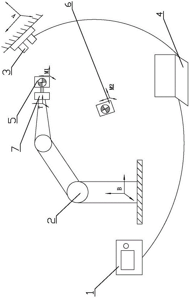
[0029] Embodiment one: as attached figure 1 , 2 As shown, the binocular stereo camera robot vision servo control device includes a robot subsystem and a vision control subsystem, and the robot subsystem includes a robot controller 1 and an articulated six-degree-of-freedom robot 2, and the vision control subsystem The system includes a binocular stereo camera 3 and a vision controller 4; the output end of the robot controller 1 is electrically connected to the input end of the articulated six-degree-of-freedom robot 2, and the two-way communication connection between the robot controller 1 and the vision controller 4 , the output end of the binocular stereo camera 3 is electrically connected to the input end of the vision controller 4 . In practical applications, the articulated six-degree-of-freedom robot 2 can be a UR5 robot produced by UniversalRobots in Denmark, which has a compact structure, light weight, and high safety; the robot controller 1 is developed based on ...

Embodiment 2

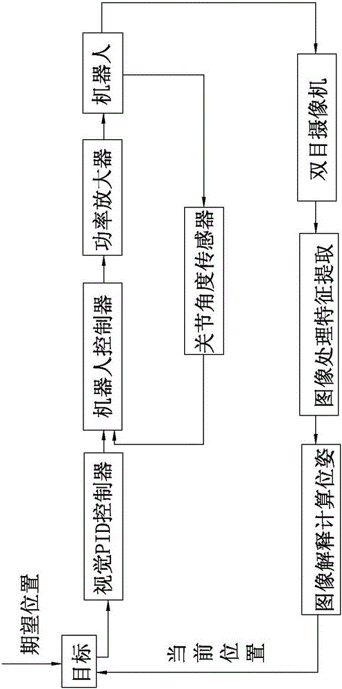
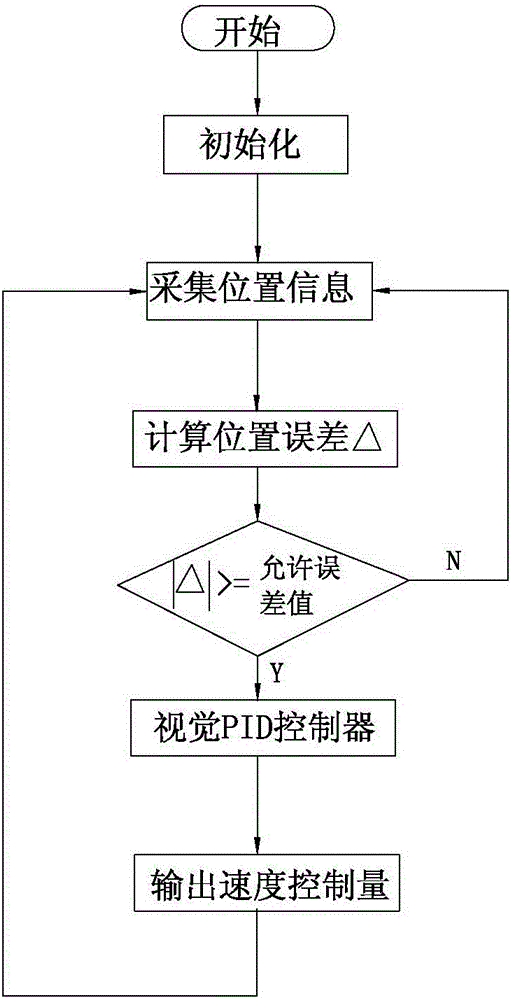
[0034] Embodiment two: if figure 1 , 2 , Shown in 3, a kind of method that uses above-mentioned binocular stereo camera robot visual servo control device, comprises the following steps:

[0035] Step 1: Start the robot subsystem and the vision control subsystem, adjust the position of the binocular stereo camera 3 to ensure that the optical target 5 of the end effector and the optical target 6 of the target moving body are both within the field of view of the binocular stereo camera 3, and then enter Step 2;

[0036] Step 2: Use the binocular stereo camera 3 to collect the position information images of the optical target 5 of the end effector and the optical target 6 of the target moving body in the initialization state, and calculate the position of the optical target 5 of the end effector in the camera coordinate system V according to the camera model homogeneous matrix expression The homogeneous matrix expression of the pose and orientation of the optical tar...


PUM


Abstract

The invention relates to the technical field of medical robots, in particular to a robot vision servo control device of a binocular three-dimensional video camera and an application method of the robot vision servo control device. The robot vision servo control device comprises a robot subsystem and a vision control subsystem. The robot subsystem comprises a robot controller and a knuckle type six-freedom-degree robot. The vision control subsystem comprises the binocular three-dimensional video camera and a vision controller. The output end of the robot controller is electrically connected with the input end of the knuckle type six-freedom-degree robot. The robot controller and the vision controller are connected through both-way communication. The output end of the binocular three-dimensional video camera is electrically connected with the input end of the vision controller. The relative position of the robot and a target is detected in real time through the fixed type binocular three-dimensional video camera, the position error is calculated, and following rapidness and accuracy of the robot are guaranteed. Collisions are avoided, the target tracking accuracy of the robot in the medical surgery is effectively improved, the surgery safety is ensured, and the risk coefficient of the surgery is lowered.

Description

technical field [0001] The invention relates to the technical field of medical robots, and relates to a binocular stereo camera robot visual servo control device and a use method thereof. Background technique [0002] At the present stage, the vision sensor is one of the most important sensors in the robot system. Its introduction has changed the requirement of the robot to accurately model the operating objects and the environment. Relying on the feedback of visual information, the robot can operate under dynamic conditions. [0003] In the medical field, visual servoing technology assists doctors in complex surgical operations by obtaining the relative positional relationship between surgical instruments and patients. For example, when performing thoracic surgery and brain surgery, with the help of the characteristics of machine vision, ray fluoroscopy and MRI images can be used to analyze and locate the lesion in detail, and control the surgical knife at the end of the...

Claims


Application Information

Patent Timeline
Patent Type & Authority Applications(China)
IPC IPC(8): B25J13/08
Inventor 曹力胡磊阿斯哈尔江·买买提依明沈晨张晓岗李国庆杨德盛胥伯勇
Owner THE FIRST TEACHING HOSPITAL OF XINJIANG MEDICAL UNIVERCITY
Why Eureka
Try Eureka