Indirect pyrolysis system and a pyrolysis method thereof

A pyrolysis and indirect technology, applied in the field of coal pyrolysis, can solve the problems of small dust content of gas and tar, large dust content of gas and tar, poor quality of gas and tar, etc., so as to reduce dust content and increase furnace Effects of Temperature, Raise and Tar Quality

Inactive Publication Date: 2015-11-25
CHANGZHENG ENG
View PDF12 Cites 6 Cited by
  • Summary
  • Abstract
  • Description
  • Claims
  • Application Information

AI Technical Summary

Problems solved by technology

[0006] The purpose of the present invention is to provide an indirect pyrolysis system and its pyrolysis method to solve the problem of poor quality of gas and tar, difficulty in separating tar, high dust content of gas and tar, low yield of tar, poor economic benefits, and large pollution and other problems, so that the quality of gas and tar is good, the difficulty of tar separation is small, the dust content of gas and tar is small, the yield of tar is high, the economic benefit is good, and the pollution is small

Method used


Image

  • Indirect pyrolysis system and a pyrolysis method thereof

Examples


Embodiment 1

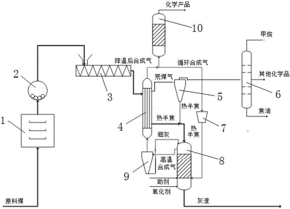
[0028] An indirect pyrolysis system, including a pulverized coal pretreatment unit, a gasification pyrolysis coupling unit, a pyrolysis product separation unit, and a synthesis gas conversion unit; the gasification pyrolysis coupling unit includes a pyrolysis furnace 4 and a high-temperature synthesis gas compressor 7 , gasifier 8 and high-temperature syngas dedusting device 9; pulverized coal pretreatment unit includes lump coal drying device 1, coal grinding device 2 and pulverized coal mechanical feeding device 3; pyrolysis product separation unit includes pyrolysis gas dedusting device 5 and pyrolysis product separation device 6; the synthesis gas conversion unit includes a synthesis gas conversion device 10; sequentially connected lump coal drying device 1, coal grinding device 2, pulverized coal mechanical feeding device 3, pyrolysis furnace 4, pyrolysis gas dedusting The device 5 and the pyrolysis product separation device 6; the pyrolysis furnace 4 is also sequentially ...

Embodiment 2

[0038] A pyrolysis method of an indirect pyrolysis system. First, the raw coal is dried through a lump coal drying device 1, and then the lump coal is pulverized into pulverized coal through a coal grinding device 2, and then fed into pyrolysis through a pulverized coal mechanical feeding device 3 Furnace 4; in the pyrolysis furnace 4, the pulverized coal on the shell side and the high-temperature syngas from the gasification furnace 8 on the tube side are exchanged for heat and pyrolysis reaction occurs to generate pyrolyzed coal gas and semi-coke substances; then, the produced The pyrolysis gas passes through the pyrolysis gas dedusting device 5 for gas-solid separation, so that the separated fine semi-coke is transported into the gasifier 8; the purified pyrolysis gas enters the pyrolysis product separation device 6 for separation to obtain pyrolysis products; The pyrolyzed semi-coke material is input into the gasifier 8; part of the syngas that has undergone heat exchange a...


PUM


Abstract

The present invention relates to an indirect pyrolysis system and a pyrolysis method thereof. The system includes a pulverized coal pretreatment unit, a gasification pyrolysis coupling unit, a pyrolysis product separation unit and a synthesis gas conversion unit. The gasification pyrolysis coupling unit includes a heat pyrolysis furnace, a high-temperature synthesis gas compressor, a gasifier and a high temperature synthesis gas removal device; the pulverized coal pretreatment unit comprises a lump coal drying device, a coal grinding machine and a pulverized coal machinery feeder; the pyrolysis product separation unit includes a pyrolysis gas dust removal device and a pyrolysis product separation device; the synthesis gas conversion unit comprises a synthesis gas conversion device; and the lump coal drying device, coal grinding machine, pulverized coal machinery feeder, pyrolysis furnace, pyrolysis gas dust removal device and pyrolysis product separation device are connected in turn. The system provided by the invention has the advantages of good quality of gas and tar, low tar separation difficulty, small amount of dust in gas and tar, high tar yield, good economic returns, and low pollution.

Description

technical field [0001] The invention belongs to the technical field of coal pyrolysis, and relates to an indirect pyrolysis system and a pyrolysis method thereof. Background technique [0002] my country is a big coal producing country in the world, and it is also a big coal consuming country. In terms of resource endowment, my country's primary energy has the characteristics of "poor oil, little gas, and rich coal". In 2010, my country's proven reserves of coal resources accounted for 93.3% of my country's fossil energy. Coal is currently the most reliable energy to ensure my country's energy security supply, and it is also the cheapest available energy at this stage. China's energy reserves, production and consumption structure determine that coal will remain the main energy source in my country for a period of time to come. The development of coal gasification technology has a history of more than 100 years, and has gradually formed a variety of technical schools such a...

Claims


Application Information

Patent Timeline
Patent Type & Authority Applications(China)
IPC IPC(8): C10J3/66C10J3/62C10J3/84C10J3/72
Inventor 王明坤姜从斌甘晓雁林东杰章刚马超
Owner CHANGZHENG ENG
Why Eureka
Try Eureka