Preparation method for bandpass optical filters with central wavelengths thereof gradually varied

A band-pass filter and center wavelength technology, applied in the direction of optical filters, can solve problems such as low production efficiency and yield, restrict development and application, and decline in yield, so as to improve production efficiency and reduce etching times , the effect of simple method

Inactive Publication Date: 2015-11-25
XIAN TECH UNIV
View PDF5 Cites 12 Cited by
  • Summary
  • Abstract
  • Description
  • Claims
  • Application Information

AI Technical Summary

Problems solved by technology

The production efficiency and yield of these two preparation methods are very low, and the preparation of a gradient filter integrating n different central wavelengths requires n coatings to achieve, and the yield is extremely low, and with the number of central wavelengths of the filter increase, its yield will drop sharply, which greatly restricts its development and application

Method used


Image

  • Preparation method for bandpass optical filters with central wavelengths thereof gradually varied
  • Preparation method for bandpass optical filters with central wavelengths thereof gradually varied
  • Preparation method for bandpass optical filters with central wavelengths thereof gradually varied

Examples


Embodiment 1

[0043] Example 1: Preparation of four filters with gradually changing central wavelengths

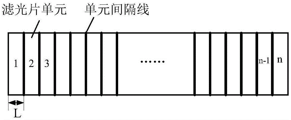
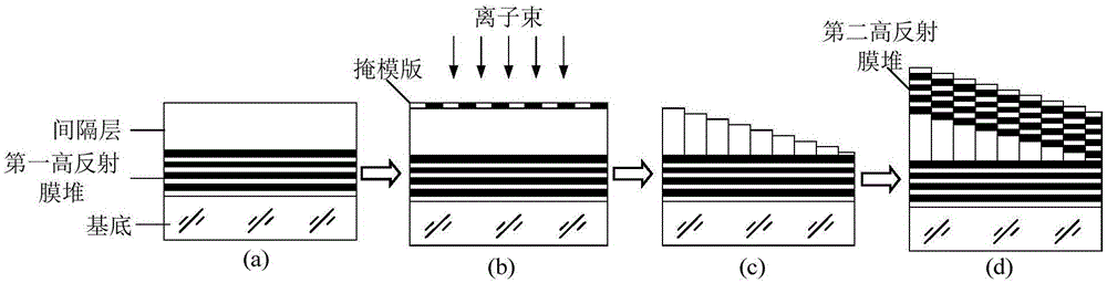
[0044] On the K9 glass substrate with a length of 10mm, a width of 10mm, and a thickness of 2mm, four filter filters with a unit filter width of 2.5mm and center wavelengths of 500nm, 540nm, 580nm and 620nm were prepared. Among them, the film structure corresponding to the narrow bandpass filter with the longest central wavelength is S / (HL) P 4.8H(LH) P / A, where H stands for SiN with high refractive index x Thin film, L stands for SiO with low refractive index x or SiO x f y The thin film has an optical thickness of 1000 Å, and the value range of p is generally between 5 and 10. The preparation process is to first deposit the structure on the substrate as S / (HL) P / A high reflective film stack 1, after depositing the high reflective film stack 1, continue to deposit SiN with a high refractive index with an optical thickness of 1.2 x thin film as a spacer layer, this completes as...

Embodiment 2

[0045] Embodiment 2: Preparation of eight optical filters with central wavelength gradient

[0046] On the K9 glass substrate with a length of 20mm, a width of 10mm, and a thickness of 2mm, the unit filter width is 2.5mm, and the center wavelengths are 500nm, 520nm, 540nm, 560nm, 580nm, 600nm, 620nm and 640nm. Eight wavelength gradients filter. Among them, the film structure corresponding to the narrow bandpass filter with the longest central wavelength is S / (HL) P 4.8H(LH) P / A, where H stands for SiN with high refractive index x Thin film, L stands for SiO with low refractive index x or SiO x f y The thin film has an optical thickness of 1000 Å, and the value range of p is generally between 5 and 10. The preparation process is to first deposit the structure on the substrate as S / (HL) P / A high reflective film stack 1, after depositing the high reflective film stack 1, continue to deposit SiN with a high refractive index with an optical thickness of x thin film as a s...


PUM


Abstract

The invention discloses a preparation method for bandpass optical filters with the central wavelengths thereof gradually varied. According to the method, firstly, a first high-reflection film stack and spacing layers are prepared in a vacuum chamber through the plasma-enhanced chemical vapor deposition process according to the proportional relationship between the locations of the central wavelengths of bandpass optical filters and the optical thicknesses of the spacing layers. Secondly, different thickness etching means are conducted on the spacing layers at different locations in the vacuum chamber based on the combination of the ion-beam etching technique and the mask plate etching technique. In this way, the spacing layers corresponding to the locations of different central wavelengths are arranged in the form of ladder-like steps. Finally, a second high-reflection film stack is prepared through the plasma-enhanced chemical vapor deposition process, so that the bandpass optical filters with the central wavelengths thereof gradually varied are obtained. According to the technical scheme of the invention, based on the above preparation method for the bandpass optical filter with the central wavelength thereof gradually varied, n bandpass optical filters with the central wavelengths thereof gradually varied can be prepared each time through the preparation process of the first high-reflection film stack and the spacing layers, the ion beam and mask plate-combined etching process and the preparation process of the second high-reflection film stack. Therefore, the method is simple and high in efficiency.

Description

technical field [0001] The invention belongs to the optical technical field of optical filter manufacture, and in particular relates to a preparation method of a band-pass optical filter with gradually changing center wavelength. Background technique [0002] The bandpass filter is in a certain wavelength band, only a small section in the middle is a high transmittance passband, and on both sides of the passband are high reflectivity stop bands. At present, there are two basic structural forms of band-pass filters. One is a band-pass filter composed of a long-wave pass film stack and a short-wave pass film stack. This filter can obtain a wider cut-off band and a deeper cutoff, but it is not easy to obtain a narrow passband; the other is a bandpass filter in the form of a Fabry-Perot interferometer, which can obtain a very narrow passband. For band-pass filters, one of the most important indicators is the center wavelength of the band-pass filter. [0003] At present, optic...

Claims


Application Information

Patent Timeline
Patent Type & Authority Applications(China)
IPC IPC(8): G02B5/20
Inventor 潘永强弥谦韩军宋俊杰杭凌侠
Owner XIAN TECH UNIV
Why Eureka
Try Eureka