Chip-on-board (COB) light source of flip chip mining lamp

A high bay lamp and flip-chip technology, applied in the field of lighting, can solve the problems that the light source cannot withstand high-frequency vibration for a long time, poor contact, light source disconnection and dead lights, etc.

Inactive Publication Date: 2015-11-25
深圳市格天光电有限公司
View PDF3 Cites 3 Cited by
  • Summary
  • Abstract
  • Description
  • Claims
  • Application Information

AI Technical Summary

Problems solved by technology

[0003] The purpose of the embodiments of the present invention is to propose a COB light source for flip-chip industrial and mining lamps, which aims to solve the problems that the LED industrial and

Method used


Image

  • Chip-on-board (COB) light source of flip chip mining lamp
  • Chip-on-board (COB) light source of flip chip mining lamp
  • Chip-on-board (COB) light source of flip chip mining lamp

Examples


Embodiment 1

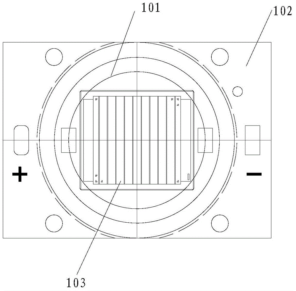
[0029] refer to figure 1 , figure 1 It is a structural schematic diagram of a COB light source for a flip-chip high bay lamp provided by an embodiment of the present invention.

[0030] exist figure 1 Among them, the COB light source of the flip-chip industrial and mining lamp includes a heat-dissipating copper substrate 102, an aluminum nitride ceramic bracket 103, and an optical glass lens 101. The aluminum oxide ceramic support 103 includes a support body made of aluminum nitride ceramics, a plurality of crystal-bonding areas are evenly arranged on one side of the support support body, and the optical glass lens 101 is pasted on the heat dissipation copper substrate 102. directly above the die package block.

[0031] An embodiment of the present invention provides a COB light source for a flip-chip high bay lamp. The COB light source for a flip-chip high bay lamp includes a heat-dissipating copper substrate, an aluminum nitride ceramic bracket, and an optical glass lens....

Embodiment 2

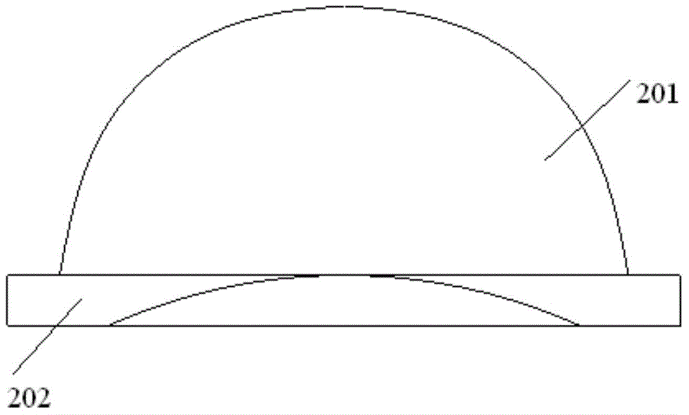
[0033] refer to figure 2 , figure 2 It is a structural schematic diagram of an optical glass lens provided by an embodiment of the present invention.

[0034] exist figure 2 Among them, there is a circular groove in the middle of the bottom of the optical glass lens 201, and the edge of the optical glass lens 201 is frosted; the optical glass lens 201 is pasted directly above the chip packaging block on the heat dissipation copper substrate .

[0035] The refractive index of the optical glass lens is 1.474.

[0036] The acid resistance of the optical glass lens reaches grade 1, and the alkali resistance reaches grade A.

[0037] The coefficient of expansion of the optical glass lens is 3.3.

[0038] Specifically, the material of the optical glass lens has the advantages of high transparency, wear resistance, smooth surface, easy cleaning, health and hygiene; the expansion coefficient of the optical glass lens is 3.3, and the expansion coefficient of high borosilicate g...

Embodiment 3

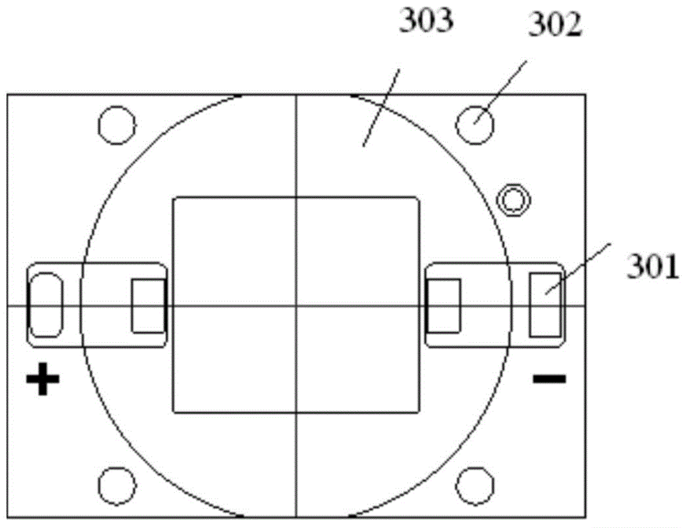
[0041] refer to image 3 , image 3 It is a schematic structural diagram of a heat dissipation copper substrate provided by an embodiment of the present invention.

[0042] exist image 3 Among them, the heat dissipation copper substrate includes a sunken platform structure 301, a through hole structure 302 and a copper foil circuit 303, and the sunken platform structure 301, the through hole structure 302 and the copper foil on the upper surface of the heat dissipation copper substrate Lines 303 and 303 are electroplated with gold.

[0043] Specifically, in image 3 Among them, the area marked by a square area such as 301 is a sunken platform structure, the area marked by a circular area such as 302 is a through-hole structure, and the area other than those marked by 301 and 302 is a copper foil circuit.

[0044] Preferably, the heat-dissipating copper substrate includes a 0.15mm deep sunken platform structure 101 and a 3.5mm through hole structure 102 .

[0045] Prefera...


PUM

PropertyMeasurementUnit
Dimensionsaaaaaaaaaa

Abstract

The embodiment of the invention discloses a chip-on-board (COB) light source of a flip chip mining lamp. The COB light source of the flip chip mining lamp comprises a cooling copper substrate, an aluminum nitride ceramic bracket and an optical glass lens, wherein the cooling copper substrate comprises a sink table structure, a through hole structure and a copper foil line; the aluminum nitride ceramic bracket comprises a bracket body which is made of aluminum nitride ceramic; a plurality of solid crystal regions are evenly arranged on one surface of the bracket body; and the optical glass lens is adhered right above a chip packaging block on the cooling copper substrate, so that the problem in a light-emitting diode (LED) light source produced by a flip chip technology is avoided; crystal fixing is realized by welding; a bonding wire is not needed; and a eutectic bracket is connected with a cooling substrate in a reflow soldering manner, so that the anti-vibration stability is very good.

Description

technical field [0001] Embodiments of the present invention relate to the technical field of lighting, and in particular to a COB light source for flip-chip industrial and mining lamps. Background technique [0002] At present, most of the high-bay lighting products used in the market are high-pressure sodium lamps, and a small part are solid-state LED lighting products produced by the traditional process of directly bonding crystals and wires on aluminum substrates, copper substrates or ceramic substrates. secondary lens. Because most ordinary LED light sources need to use insulating glue or silver glue to bond the die, their thermal resistance is generally 12°C / W, which is relatively high, and there is a big problem in the heat dissipation of the light source. In addition, the LED light source made by the traditional wire bonding process cannot withstand large pulse currents, let alone work stably for a long time under the drive of high current; excessive pulse current or...

Claims


Application Information

Patent Timeline
IPC IPC(8): H01L33/48H01L33/64H01L33/58
CPCH01L33/647H01L33/48H01L33/58
Inventor 王志成朱正光
Owner 深圳市格天光电有限公司
Why Eureka
Try Eureka