Airflow energy-saving drying device and airflow energy-saving drying method

A technology of airflow drying and drying equipment, which is applied in the direction of drying gas arrangement, drying solid materials, lighting and heating equipment, etc. It can solve the problems of reduced mass transfer driving force, less heat recovery, and failure to achieve the expected drying effect. The effect of reducing the amount of electricity and reducing power consumption

Active Publication Date: 2015-12-02
ACAD OF ENVIRONMENTAL PLANNING & DESIGN GRP CO LTD NANJING UNIV
View PDF10 Cites 19 Cited by
  • Summary
  • Abstract
  • Description
  • Claims
  • Application Information

AI Technical Summary

Problems solved by technology

For a multi-stage drying system, the first method is completely ineffective, the second method has wide applicability, but has less heat recovery, and the third method uses more waste heat, but with the accumulation of moisture in the air, the mass transfer driving force decreases Small, even unable to achieve the expected drying effect

Method used


Image

  • Airflow energy-saving drying device and airflow energy-saving drying method
  • Airflow energy-saving drying device and airflow energy-saving drying method

Examples


Embodiment 1

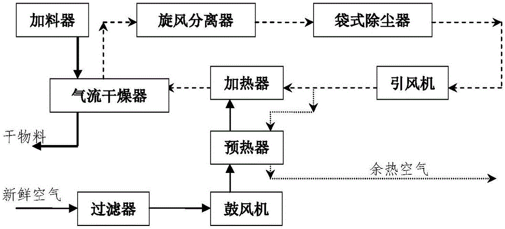
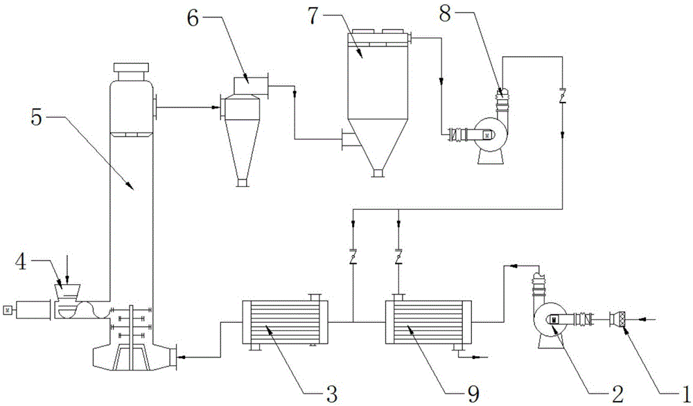
[0028] An airflow energy-saving drying equipment, such as figure 2 As shown, the airflow energy-saving drying equipment provided by the present invention includes: filter 1, blower 2, heater 3 (heater is a steam heater), feeder 4, airflow dryer 5 (airflow dryer is a straight tube airflow dryer ), cyclone separator 6, bag filter 7, induced draft fan 8, preheater 9 (the preheater is a heat pipe preheater). Wherein the filter 1 is connected with the inlet of the blower 2; the outlet of the blower 2 is connected with the heat pipe preheater 9, and the outlet of the heat pipe preheater 9 is connected with the inlet of the heater 3; the outlet of the steam heater 3 is connected with the inlet of the airflow dryer 5; The outlet of the dryer 5 is connected to the cyclone separator 6; the outlet of the cyclone separator 6 is connected to the inlet of the bag filter 7; the outlet of the bag filter 7 is connected to the inlet of the induced draft fan 8; the outlet of the induced fan 8 i...

Embodiment 2

[0036] A kind of airflow energy-saving drying equipment, the airflow energy-saving drying equipment provided by the invention comprises: filter 1, blower 2, heater 3 (heater is steam heater), feeder 4, airflow dryer 5 (airflow dryer is pulse Airflow dryer), cyclone separator 6, bag filter 7, induced draft fan 8, preheater 9 (preheater is a finned tube preheater). Wherein said filter 1 is connected with the inlet of blower 2; outlet of blower 2 is connected with inlet of steam heater 3; outlet of steam heater 3 is connected with inlet of airflow dryer 5; outlet of airflow dryer 5 is connected with cyclone separator 6; cyclone separation The outlet of filter 6 is connected to the inlet of bag filter 7; the outlet of bag filter 7 is connected to the inlet of induced draft fan 8; the outlet of induced draft fan 8 is connected to the inlet of steam heater 3; the outlet of feeder 4 is connected to the inlet of air dryer 5; the outlet of induced draft fan 8 At the same time, it is co...

Embodiment 3

[0044]An airflow energy-saving drying equipment, the airflow energy-saving drying equipment provided by the invention comprises: a filter 1, a blower 2, a heater 3 (the heater is an auxiliary electric heater), a feeder 4, an airflow dryer 5 (the airflow dryer is Rotating flash stream dryer), cyclone separator 6, bag filter 7, induced draft fan 8, preheater 9 (the preheater is a heat pipe heat exchanger). The filter 1 is connected to the inlet of the blower 2; the outlet of the blower 2 is connected to the preheater 9; the outlet of the preheater 9 is connected to the inlet of the electric heater 3; the outlet of the electric heater 3 is connected to the inlet of the airflow dryer 5; the airflow drying The outlet of device 5 is connected to cyclone separator 6; the outlet of cyclone separator 6 is connected to the inlet of bag filter 7; the outlet of bag filter 7 is connected to the inlet of induced draft fan 8; the outlet of induced fan 8 is connected to the inlet of electric h...


PUM


Abstract

The invention discloses an airflow energy-saving drying device and an airflow energy-saving drying method and belongs to the field of drying and energy saving. The device comprises a filter (1), an air blower (2), a heater (3), a feeder (4), an airflow dryer (5), a cyclone separator (6), a bag dust remover (7), an induced draft fan (8) and a pre-heater (9), wherein the filter (1) is connected to an inlet of the air blower (2); the air blower (2) is connected to an inlet of the pre-heater (9); an outlet of the pre-heater (9) is connected to an inlet of the heater (3); an outlet of the heater (3) is connected to an inlet of the airflow dryer (5); the airflow dryer (5), the cyclone separator (6), the bag dust remover (7) and the induced draft fan (8) are connected with one another in sequence; an outlet of the induced draft fan (8) is simultaneously connected with the pre-heater (9) and the heater (3). The airflow energy-saving drying device and the airflow energy-saving drying method are capable of recycling the waste heat of the airflow drying tail gas to the maximum extent; the problem of accumulation of moisture in circulating air is solved; the operation load of the device is effectively reduced.

Description

technical field [0001] The invention relates to an airflow energy-saving drying device and an airflow energy-saving drying method, in particular to a sludge drying device and process using hot air as a drying medium and closed-circuit circulation of waste heat tail gas. Background technique [0002] According to statistics, the drying energy consumption of various industries in the UK accounts for about 8% of the total energy consumption of industrial systems, and 12% in my country. At present, the utilization rate of drying energy in my country's general chemical industry production is only 20% to 60%. Most of the energy is discharged with the tail gas, resulting in a large degree of waste of resources and energy. Therefore, the utilization of waste heat from drying exhaust gas is an important direction of drying and energy saving research. [0003] At present, the utilization of waste heat from air-flow drying tail gas has gradually attracted the attention of engineering ...

Claims


Application Information

Patent Timeline
Patent Type & Authority Applications(China)
IPC IPC(8): F26B21/02F26B25/00F26B25/22C02F11/12
CPCY02P70/10
Inventor 李明陆朝阳樊健胡昌旭费正连姚琪
Owner ACAD OF ENVIRONMENTAL PLANNING & DESIGN GRP CO LTD NANJING UNIV
Why Eureka
Try Eureka