A multi-stage recovery and comprehensive utilization system of flue gas waste heat in a cogeneration power plant

A flue gas waste heat and thermoelectric technology, which is applied in the direction of combined combustion mitigation, preheating, and feed water heaters, can solve the problems of low-temperature corrosion of the air preheater, large exhaust smoke loss, and low efficiency of waste heat utilization, etc., to improve the inlet temperature , Prevent low temperature corrosion, meet the effect of heat load demand

Active Publication Date: 2017-06-27
HUANENG JILIN POWER GENERATION JIUTAI ELECTRIC FACTORY +1
View PDF1 Cites 1 Cited by
  • Summary
  • Abstract
  • Description
  • Claims
  • Application Information

AI Technical Summary

Problems solved by technology

[0008] In order to overcome the above-mentioned shortcomings of the prior art, the object of the present invention is to provide a multi-stage recovery and comprehensive utilization system for waste heat of flue gas in a combined heat and power plant, which solves the problems of high exhaust gas temperature and large exhaust gas loss in the power plant, and improves the operation of the power plant. Economical, it also solves the problem of low-temperature corrosion of the air preheater, and solves the problem that the waste heat utilization system cannot heat the return water of the heating network in winter, and the waste heat utilization efficiency is not high. In addition, by opening and closing the valve and controlling the flow path of the working fluid, It can flexibly switch between different waste heat utilization methods according to actual working conditions

Method used


Image

  • A multi-stage recovery and comprehensive utilization system of flue gas waste heat in a cogeneration power plant

Examples


Embodiment Construction

[0027] The implementation of the present invention will be described in detail below in conjunction with the drawings and examples.

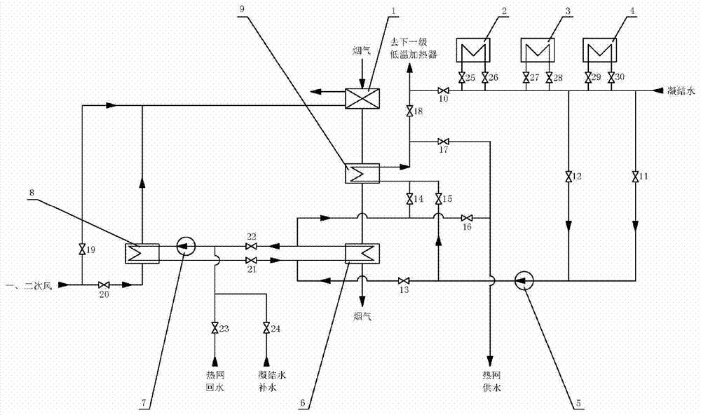
[0028] Such as figure 1 As shown, the flue gas waste heat multi-stage recovery and comprehensive utilization system of a combined heat and power plant includes an air preheater 1, a sixth low-temperature heater 2, a seventh low-temperature heater 3, an eighth low-temperature heater 4, condensate pumps 5, and two Level 1 flue gas cooler 6, closed circulation water pump 7, air heater 8, level 1 flue gas cooler 9 and related connecting pipelines, valves, etc.

[0029] Condensate water inlet is divided into two ways, through the pipe,

[0030] One path is connected to the water inlet of the condensate pump 5 through the eleventh cut-off valve 11; The primary low temperature heater is connected.

[0031] The 30th stop valve 30 is set at the entrance of the eighth low temperature heater 4, the 29th stop valve 29 is set at the outlet, the 28th stop ...


PUM


Abstract

A multi-stage recovery and comprehensive utilization system for flue gas waste heat in a combined heat and power plant, in which a primary flue gas cooler and a secondary flue gas cooler are arranged in the flue downstream of the air preheater, and a secondary flue gas cooler and air heater A closed water cycle is arranged between them to realize the full use of the waste heat of the flue gas; during the heating period, the waste heat of the heating network return water and the primary and secondary air are used to recover the waste heat to increase the inlet temperature of the air side of the air preheater and prevent low-temperature corrosion; During the heating period, use condensed water to replenish water to absorb the waste heat of flue gas, and can also heat the primary and secondary air at the same time to increase the inlet temperature of the air side of the air preheater and prevent low-temperature corrosion of the air preheater; it is arranged in the downstream flue of the air preheater The two-stage flue gas cooler uses condensed water and heating network return water as working fluids to absorb the waste heat of flue gas; the invention can separately and simultaneously heat the heating network return water, condensed water, and primary and secondary air, realizing The multi-level and efficient utilization of flue gas waste heat meets the switching between heating and non-heating periods of heat load.

Description

technical field [0001] The invention belongs to the technical field of comprehensive utilization of flue gas waste heat in cogeneration power plants, and in particular relates to a multi-stage recycling and comprehensive utilization system for flue gas waste heat in cogeneration power plants. Background technique [0002] my country has promised to reach the peak of carbon dioxide emissions in 2030. In the next 15 years, my country's pressure on energy conservation and emission reduction will be enormous. Coal-fired power plants are the main source of carbon dioxide emissions. Energy saving and consumption reduction are of great significance for controlling carbon dioxide emissions and improving the economic benefits of power plants. Among the main heat losses of boilers in power plants, exhaust smoke loss is the largest item, accounting for more than 70% of the total heat loss. According to experience, the boiler efficiency will increase by 0.5-0.65% for every 10°C decreas...

Claims


Application Information

Patent Timeline
Patent Type & Authority Patents(China)
IPC IPC(8): F22D1/36
CPCY02E20/14
Inventor 时正海唐巍高洪培肖平
Owner HUANENG JILIN POWER GENERATION JIUTAI ELECTRIC FACTORY
Why Eureka
Try Eureka