Automatic biomass particle heating stove and ignition method thereof

A biomass pellet and heating stove technology, which is applied in heating methods, household stoves/stoves, stoves/stoves with hot water devices, etc., can solve the problems of indoor environmental impact, low ignition success rate, and black smoke generation. Achieve the effect of ensuring combustion adequacy, reducing atmospheric emissions, and automatically adjusting air volume

Inactive Publication Date: 2015-12-23
山东宇龙机械有限公司
View PDF7 Cites 5 Cited by
  • Summary
  • Abstract
  • Description
  • Claims
  • Application Information

AI Technical Summary

Problems solved by technology

[0005] The degree of automatic control is not high, and the heating is unstable
Although automatic screw feeding is used in the feeding process, since the screw feeding cylinder is directly connected to the furnace, when the open flame generated by burning in the furnace, the high temperature brought by the open flame will burn the remaining biomass fuel in the screw feeding cylinder Early carbonization will generate black smoke during the period, and the generated black smoke will easily affect the indoor environment, and the screw feeding cylinder will be easily damaged when exposed to high temperature, resulting in intermittent feeding, which greatly reduces the heating exp

Method used


Image

  • Automatic biomass particle heating stove and ignition method thereof
  • Automatic biomass particle heating stove and ignition method thereof
  • Automatic biomass particle heating stove and ignition method thereof

Examples


Embodiment Construction

[0057] In order to facilitate the understanding of the technical content of the present invention, the technical solutions thereof will be further described below in conjunction with the accompanying drawings.

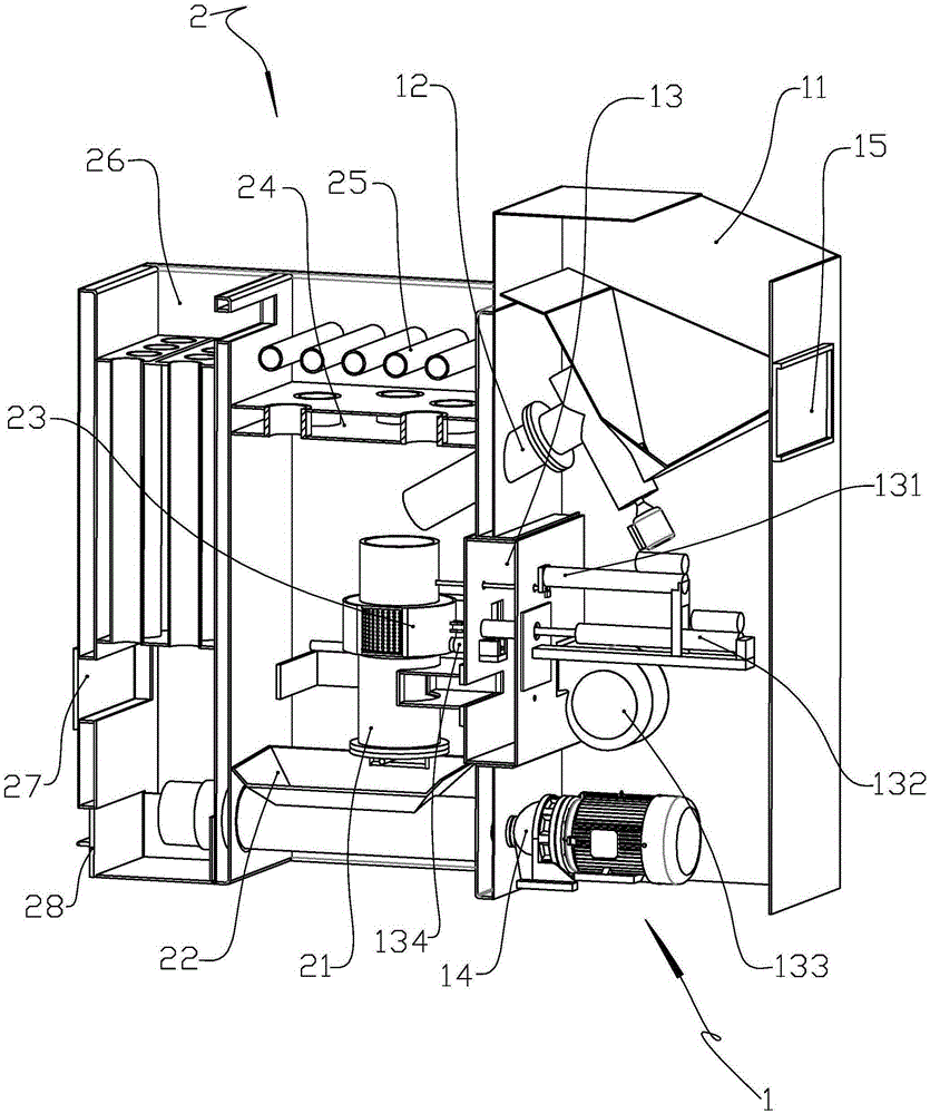
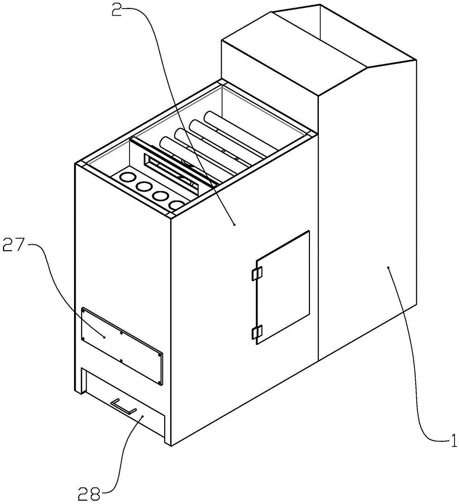
[0058] Such as figure 1 , figure 2 A biomass particle automatic heating furnace shown includes a control box 1 and a furnace box 2 connected to the left side of the control box 1 .

[0059] The upper cavity of the control box 1 is set as a granule bin 11, and the lower end of the granule bin 11 is funnel-shaped. A feeding auger device is arranged on the left side outer wall of the funnel-shaped part at the lower end of the particle bin 11, so that the axial direction of the auger feeding cylinder in the feeding auger device is arranged obliquely upward. And the feeding tube 12 is set on the upper end of the auger feeding tube, the feeding tube 12 is axially inclined downward, and one end passes through the partition between the control box 1 and the furnace box 2 an...


PUM


Abstract

The invention discloses an automatic biomass particle heating stove. According to the automatic biomass particle heating stove, a combustion chamber and a feeding auger are arranged in a spaced mode, a feeding cylinder corresponding to the combustion chamber is arranged at the tail conveying end of the feeding auger, and thus the problem of carbonization of participating fuel in the feeding auger is solved; through the additional arrangement of a control panel, a driving device, a temperature measurement device, a deslagging auger and the like, automatic control over feeding, ignition, deslagging and the air volume is achieved, and automation is achieved; a vertical and tangential bidirectional air inlet mode is adopted, in this way, oxygen-enriched and suspension combustion is achieved, and sufficient fuel is guaranteed; a two-stage dedusting channel is arranged for smoke, in this way, the degree of pollution of exhausted smoke can be lowered, and the environmental friendless effect is achieved; both the deslagging portion and the dedusting portion are arranged in a stove body and are sealed relative to the indoor space when the heating stove operates, and thus indoor cleanliness can be guaranteed when the heating stove is in use; a time-control ignition mode and a temperature-control ignition mode are adopted, and the ignition mode can be selected according to different times; meanwhile, in the temperature-control ignition mode, the success rate of ignition can be greatly increased, the flameout situation can be found in time and ignition can be started immediately.

Description

technical field [0001] The invention relates to a combustion device which uses biomass particle fuel as an energy source to burn to generate heat energy, and belongs to the technical field of heating furnaces. Background technique [0002] In northern regions, heating furnaces are commonly used to heat water in winter. At present, by using biomass heating stoves instead of coal, the smoke and other harmful gases produced during the burning of coal can be reduced, and a large amount of agricultural waste can be utilized at the same time. Biomass particles are mostly made of rice husks, corn husks, cottonseed husks, etc., which are crushed into a particle molding machine, and the shape is block, rod or round particles. Moreover, with the continuous deepening of wood processing and the implementation of the concept of recycling, wood chip biomass fuel is also relatively common. [0003] In short, the raw materials used as biomass fuel are becoming more and more diversified, a...

Claims


Application Information

Patent Timeline
IPC IPC(8): F24B1/183F24B1/191
Inventor 郭成军
Owner 山东宇龙机械有限公司
Why Eureka
Try Eureka