Flue gas dust removal, desulfurization and denitrification coprocessing technology

A technology for synergistic treatment, desulfurization and denitrification, which is applied in the comprehensive treatment of coke oven flue gas and sintering pellets in iron and steel enterprises.

Active Publication Date: 2015-12-30
JIGANG INT ENG & TECH CO LTD
View PDF5 Cites 13 Cited by
  • Summary
  • Abstract
  • Description
  • Claims
  • Application Information

AI Technical Summary

Problems solved by technology

[0006] The purpose of the present invention is to provide a flue gas dedusting, desulfurization and denitrification collaborative treatment process, which is aimed at the deficiency of desulfurization but not denitrification in the flue gas treatment of existing iron and steel enterprises, the deficiency of large energy consumption in denitrification such as the existing SCR method, and the insufficiency of desulfurization and denitrification. In order to solve the problem of low efficiency of integrated denitrification, a co-treatment process of flue gas dust removal, desulfurization and denitrification is provided. This process can not only improve the existing desulfurization device to reduce the total emission of sulfur dioxide and nitrogen oxides, but also achieve high-efficiency denitrification Low-cost operation under certain conditions, with high economic, environmental and social benefits

Method used


Image

  • Flue gas dust removal, desulfurization and denitrification coprocessing technology
  • Flue gas dust removal, desulfurization and denitrification coprocessing technology
  • Flue gas dust removal, desulfurization and denitrification coprocessing technology

Examples


Embodiment Construction

[0030] A flue gas dedusting, desulfurization and denitrification cooperative treatment process described in the present invention, the steps are as follows:

[0031] ① Desulfurization

[0032] Nitrogen oxide content 300mg / Nm 3 , sulfur dioxide content 1500mg / Nm 3 The flue gas is introduced into the desulfurization tower; the parameters of the flue gas discharged after semi-dry desulfurization of the desulfurization tower are: temperature 80°C, dust concentration 20mg / Nm 3 , nitrogen oxide content 300mg / Nm 3 , sulfur dioxide content ≤ 200mg / Nm 3 ; The desulfurization tower is an existing semi-dry desulfurization device.

[0033] ② Dust removal

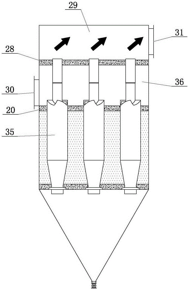
[0034] The flue gas desulfurized by step ① is introduced into the dust removal device for dust removal treatment;

[0035] ③Uniform air distribution and ammonia injection

[0036] Step ② The flue gas after dedusting is guided by a guide tube to make it evenly distributed and stable in flow, and ammonia gas is sprayed into the flu...


PUM

PropertyMeasurementUnit
thicknessaaaaaaaaaa

Abstract

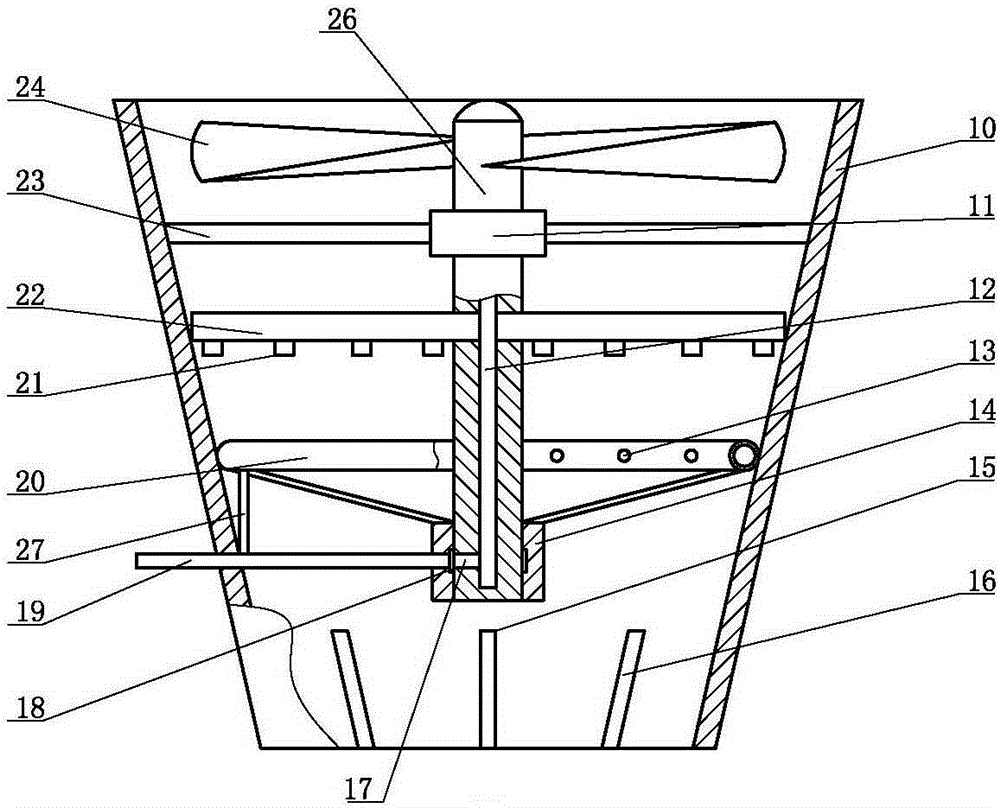
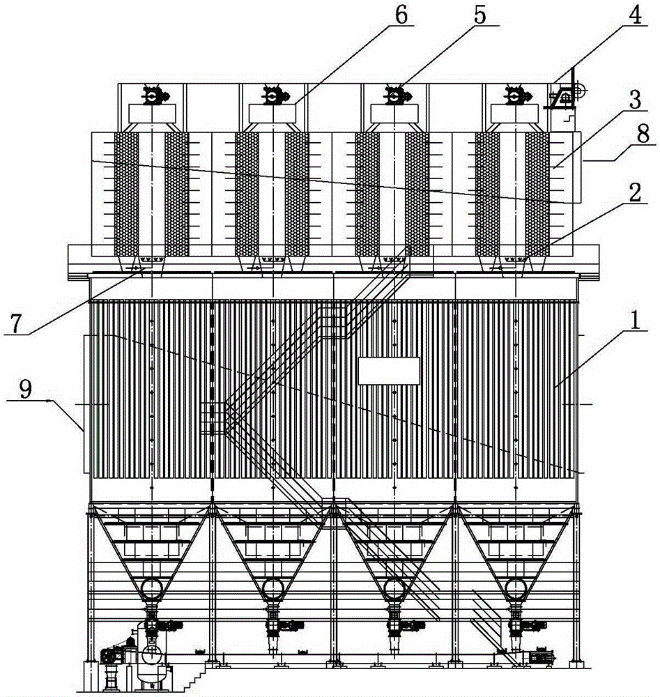
A flue gas dust removal, desulfurization and denitrification coprocessing technology comprises a housing, wherein the housing is an increasing coupling from bottom to top; a support is mounted at the inner upper part of the housing; a first shaft sleeve is arranged in the middle of the support; a rotating shaft is mounted in the first shaft sleeve; an impeller and an ammonia injection pipe are mounted on the rotating shaft; the ammonia injection pipe is located below the impeller; second nozzles of which the openings face downwards are arranged on the ammonia injection tube; an air passage is formed in the rotating shaft and communicated with the ammonia injection tube; a side hole is formed in the lower part of the rotating shaft and communicated with the air passage; a second shaft sleeve is mounted at the lower part of the rotating shaft; a first guide plate and two second guide plates are mounted in the bottom of the housing; the two guide plates define an increasing channel from bottom to top; a ring-shaped ammonia injection pipe is located between the ammonia injection pipe and the first guide plate. According to the flue gas dust removal, desulfurization and denitrification coprocessing technology, nitrogen oxides in flue gas are effectively removed after semi-dry desulfuration, the defect that fluorides cannot be integrally removed by active coke is overcome; consumption of a heat source and increase of the flue gas temperature are not needed during low-temperature denitrification, so that lots of energy is saved in comparison with an SCR (Selective Catalytic Reduction) denitrification process.

Description

technical field [0001] The invention relates to the field of comprehensive treatment of sintering pellets and coke oven flue gas in iron and steel enterprises, specifically a flue gas dust removal, desulfurization and denitrification cooperative treatment process. Background technique: [0002] Among the sintering flue gas treatment projects that have been put into operation or are under construction in China, only desulfurization without denitrification accounts for more than 98%, and few integrate desulfurization and denitrification. In terms of denitrification alone, the relatively mature flue gas denitrification technologies are mainly Selective catalytic reduction technology (SelectiveCatalyticReduction, referred to as SCR) and selective non-catalytic reduction technology (SelectiveNon-CatalyticReduction, referred to as SNCR). In addition, there are some technologies for wet removal of nitrogen oxides. [0003] Selective non-catalytic reduction technology (SNCR): Selec...

Claims


Application Information

Patent Timeline
Patent Type & Authority Applications(China)
IPC IPC(8): B01D53/75B01D53/90B01D53/80B01D53/50B01D53/56B01D46/02B01D45/14B01D46/00
Inventor 马秀珍栾元迪尹雄峰梁敬斌
Owner JIGANG INT ENG & TECH CO LTD
Why Eureka
Try Eureka