Supercharge Your Innovation With Domain-Expert AI Agents!

U-row continuous extrusion die for metal special-shaped

An extrusion die and special-shaped technology, which is applied in the continuous extrusion die of metal special-shaped U-rows, and the field of making conductive heterogeneous U-rows, which can solve the problems of excessive size deviation of the head and tail of the extruded profile, poor forming conditions, mold materials, and high performance requirements. increase and other problems, to achieve uniform and stable metal flow speed, which is beneficial to subsequent processing and saves labor costs

Active Publication Date: 2017-03-22
JIANGYIN ELECTRICAL ALLOY
View PDF4 Cites 0 Cited by
  • Summary
  • Abstract
  • Description
  • Claims
  • Application Information

AI Technical Summary

Problems solved by technology

[0007] 3. The horizontal extrusion temperature is generally around 750°C, and the extrusion force is around 700t. Therefore, the harsh forming conditions require high mold material performance and increase the cost of mold manufacturing.
[0009] 5. The temperature and pressure required for horizontal extrusion are higher than those for continuous extrusion, so it is easily affected by temperature during the production process, resulting in uneven metal flow, which leads to excessive size deviation of the head and tail of the extruded profile, which is not conducive to subsequent processing; Continuous extrusion is very stable in the production process. The small extrusion force can control the flow of metal well and the extruded profile has uniform size.
[0010] There are still big problems in the continuous extrusion of U-shaped rows, which are as follows: first, the uneven flow of metal during the continuous extrusion process will easily lead to difficulty in filling the U-shaped mouth and cannot fill the guaranteed size; the second is that , it is easy to cause the metal flow at the bottom of the U-shape to be faster than the mouth, resulting in warpage of the profile; third, it is difficult to achieve a mold structure design with uniform metal flow at the outlet mouth and the bottom

Method used


Image

  • U-row continuous extrusion die for metal special-shaped
  • U-row continuous extrusion die for metal special-shaped
  • U-row continuous extrusion die for metal special-shaped

Examples


specific Embodiment

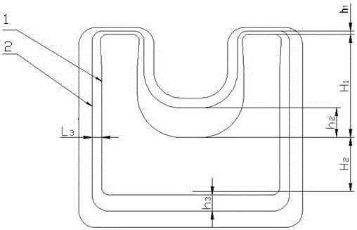
[0047] Such as Figure 9 , Figure 10 As shown, the sizing area of ​​the mold body is 4-8mm long; the angle formed by each side wall of the flow-promoting zone and the axis line of the mold body is 35°, and the length of the flow-promoting zone is L 1 =3mm; the angle formed by each side wall of the transition zone and the axis of the mold is α5°, and the length of the transition zone is L 1 =3mm; the flow-promoting zone and the transition zone, the transition zone and the sizing zone are smoothly connected by an arc; the flow-blocking zone is 9-5, 9-6, and the angle between the flow-stopping zone and the axis line of the mold body is 10°, and the inner U The type adopts no bevel design, that is, the bevel angle is 0°. Such as Figure 8 , Figure 11 , Figure 12 As shown, the outlet section of the gasket is translated by h1=2mm, h2=1.5 mm, h3=4 mm, h4=19.5 mm by each side of the inlet section of the mold body, and the side wall of the gasket flow-promoting area and the axi...


PUM


Abstract

The invention relates to a metal specially-shaped U-bar continuous extrusion die which is characterized by comprising a die main body (1), a pad (2) and a cavity (3), wherein a flow promoting region (1.1) and a transitional region (1.2) are designed at the opening part of a U-shaped bar of the die main body (1) in sequence from the front end to the rear end; a flow blocking region (1.5), a diameter fixing region (1.3) and an avoiding region (1.4) are designed in other regions of the die main body (1) in sequence from the front end to the rear end; the flow blocking region (1.5) is outwards unfolded to the front end direction of the die main body (1); the flow promoting region (1.1), the transitional region (1.2), the diameter fixing region (1.3) and the avoiding region (1.4) are connected in sequence in a penetrating manner; and the flow blocking region (1.5), the diameter fixing region (1.3) and the avoiding region (1.4) are connected in sequence in a penetrating manner. The die capable of adopting a continuous extrusion production technology can overcome the shortcomings of a horizontal extrusion production technology, so that the production cost is reduced, the production efficiency is improved, and the product quality is improved.

Description

technical field [0001] The invention relates to the field of metal thermoforming, in particular to a metal special-shaped U-bar continuous extrusion die, which is mainly used for making conductive heterogeneous U-bars. Background technique [0002] Metal shaped bars mainly include copper bars and aluminum bars. For example, copper bars have good electrical conductivity, good mechanical properties, good ductility and reliability, so copper bars, as a high-current conductive product, are suitable for high and low voltage electrical appliances, switch contacts, power distribution equipment, and bus ducts It is also widely used in metal smelting, electrochemical plating, chemical caustic soda and other super-high current electrolytic smelting projects. [0003] Special-shaped rows such as U-shaped, special-shaped U-shaped, and ordinary U-shaped are usually uniform in size, relatively large in height and width; U-shaped rows usually have grooves and other shapes that cause large...

Claims


Application Information

Patent Timeline
Patent Type & Authority Patents(China)
IPC IPC(8): B21C25/02
CPCB21C25/02
Inventor 冯岳军张光亮张涛赵强赵永好王雪杨亚楠
Owner JIANGYIN ELECTRICAL ALLOY
Features
  • R&D
  • Intellectual Property
  • Life Sciences
  • Materials
  • Tech Scout
  • Unparalleled Data Quality
  • Higher Quality Content
  • 60% Fewer Hallucinations
Learn More