Photoelectrochemistry detection device with double detection pools and use method of photoelectrochemistry detection device
A photoelectrochemical and detection device technology, applied in the field of photoelectrochemistry, can solve the problems of limiting the detection sensitivity of photoelectrochemical sensors, the determination of unfavorable trace components, and a single detection cell, so as to achieve accurate and reliable experimental results, and facilitate integration and miniaturization. , the small effect of the detection instrument
- Summary
- Abstract
- Description
- Claims
- Application Information
AI Technical Summary
Problems solved by technology
Method used
Image

Examples
Embodiment 1
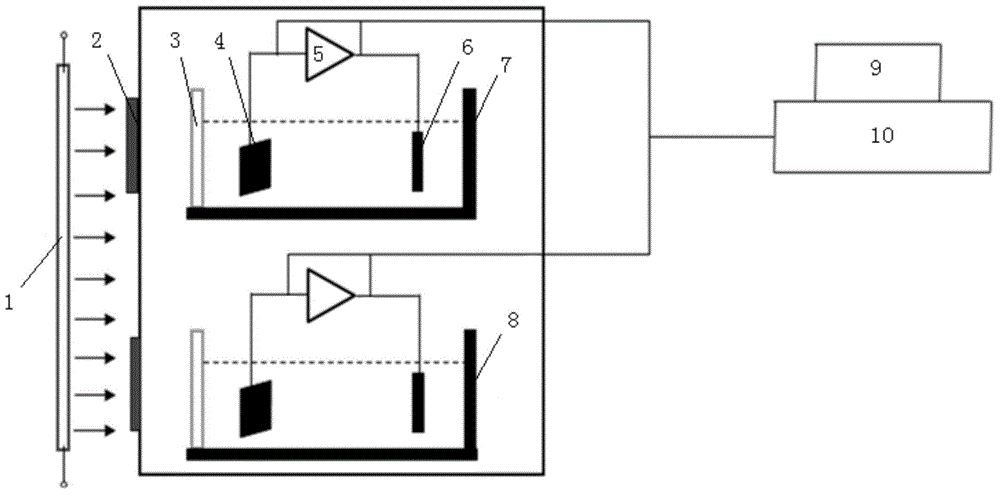
[0047] A first resistor 5 is connected between the first photosensitive electrode 4 and the first pair of electrodes 6 , and the dual-channel chromatography workstation 10 measures the voltage shared by the first resistor 5 . A second resistor is connected between the second photosensitive electrode and the second pair of electrodes, and the dual-channel chromatography workstation 10 measures the voltage shared by the second resistor. Since the current generated under light conditions is small and the resistance of the electrolyte solution is large, the sampling resistor must reach a certain resistance value to detect the voltage signal. The first resistor 5 and the second resistor are provided with resistor selection knobs. Different gears are selected according to different systems, a trimming resistor is connected between the second photosensitive electrode and the second pair of electrodes, and the trimming resistor can be used to balance the background current of the sampl...
Embodiment 2
[0049] A first current-voltage converter is connected between the first photosensitive electrode 4 and the first pair of electrodes 6 , and a second current-voltage converter is connected between the second photosensitive electrode and the second pair of electrodes. The photocurrent is converted into a voltage signal after passing through the converter, and the voltage signal is proportional to the magnitude of the photocurrent and the amplification factor of the converter, without using a sampling resistor.
[0050] The light valve 2 assembly is arranged on the side of the sample cell 7 and the reference cell 8, the side of the sample cell 7 and the reference cell 8 close to the light source 1 is the light window 3, and the material of the light window 3 is optical quartz glass. At this time, the light source 1 is arranged on the side of the dark box.
Embodiment 3
[0052] The sample cell 7 and the reference cell 8 are respectively provided with a first reference electrode and a second reference electrode, the first reference electrode is connected to the first photosensitive electrode 4 , and the second reference electrode is connected to the second photosensitive electrode. A first current-voltage converter is connected between the first photosensitive electrode 4 and the first pair of electrodes 6 , and a second current-voltage converter is connected between the second photosensitive electrode and the second pair of electrodes. The three-electrode system can stabilize the electrode potentials of the first photosensitive electrode and the second photosensitive electrode at a set value, eliminate the influence of charging current, and make the differential response signal more stable, especially suitable for systems with small photocurrents.
[0053] The light valve 2 assembly is arranged above the sample pool 7 and the reference pool 8, ...
PUM
| Property | Measurement | Unit |
|---|---|---|
| length | aaaaa | aaaaa |
| width | aaaaa | aaaaa |
Abstract
Description
Claims
Application Information
 - R&D
- Intellectual Property
- Life Sciences
- Materials
- Tech Scout
- Unparalleled Data Quality
- Higher Quality Content
- 60% Fewer Hallucinations
Browse by: Latest US Patents, China's latest patents, Technical Efficacy Thesaurus, Application Domain, Technology Topic, Popular Technical Reports.
© 2025 PatSnap. All rights reserved.Legal|Privacy policy|Modern Slavery Act Transparency Statement|Sitemap|About US| Contact US: help@patsnap.com